
Image recording apparatus, method of generating print data for the same, and control program for implementing the method

a technology of image recording and print data, which is applied in the direction of still video cameras, instruments, visual presentations, etc., can solve the problems of inability to apply a technique to a system, the top-bottom orientation of the resulting image may not be uniform from one another, and the top-bottom orientation of the object may not match the top-bottom orientation of the image data, etc., to achieve favorable print layout and low cost

Inactive Publication Date: 2006-06-15
CANON KK
View PDF5 Cites 20 Cited by
  • Summary
  • Abstract
  • Description
  • Claims
  • Application Information

AI Technical Summary

Benefits of technology

[0012] It is a first object of the present invention to provide an image recording apparatus and a print data generating method for the same, that are capable of realizing a favorable print layout where bottom orientations of image data are made uniform easily and at low cost, and a control program for implementing the method.
[0015] According to the above construction, it is possible to realize a favorable print layout where orientations (for example, bottom orientations) of image data are made uniform easily and at low cost. In addition, it is possible to make uniform the bottom orientations of an entire layout including not only image data but also objects.
[0019] According to the above construction, it is possible to realize a favorable print layout where orientations (for example, bottom orientations) of image data are made uniform easily and at low cost. In addition, it is possible to make uniform the bottom orientations of an entire layout including not only image data but also objects.
[0023] Even more preferably, the image recording apparatus comprises a memory with a limitation of being incapable of storing an entire decoding result obtained when the plurality of image dada are decoded, and the bottom orientation uniforming device comprises a combination detecting device that detects a combination of the respective rotation information of the plurality of image data that minimizes a processing load of a process to be carried out by the bottom orientation uniforming device to obtain the image data having been rotated, and an image rotating section that rotates the plurality of image data in accordance with the combination detected by the combination detecting device.
[0026] According to the above construction, it is possible to realize a favorable print layout where orientations (for example, bottom orientations) of image data are made uniform easily and at low cost. In addition, it is possible to make uniform the bottom orientations of an entire layout including not only image data but also objects.
[0031] According to the above construction, it is possible to realize a favorable print layout where orientations (for example, bottom orientations) of image data are made uniform easily and at low cost. In addition, it is possible to make uniform the bottom orientations of an entire layout including not only image data but also objects.

Problems solved by technology

When it is necessary to rotate images for the orientation alignment, if a method is used that rotates the images by 90° in the same direction every time, the images will be laid out with no consideration whatsoever as to the “top-bottom orientations” of respective images, and therefore the following problems occur.
(1) When a plurality of image data are laid out on a single print medium, the top-bottom orientations of the resulting images may not be uniform from one another.
(2) When using a layout where in addition to image data, objects whose top-bottom orientations should be properly aligned are inserted, the top-bottom orientations of the objects may not match the top-bottom orientations of the image data.
However, this technique cannot be applied to a system such as a modern digital camera where images picked up with the camera held in a vertical posture are recorded as landscape images.
In the technique disclosed in Japanese Patent Publication No. 3082982, although it is certainly possible to solve the problem (1), to realize such technique, a display device for displaying the image data, a memory for storing the image data to be displayed, and the like are required, resulting in the unavoidable increased cost of providing such equipment.
Also, when there is a large amount of image data to be printed, it will be necessary to display all of the image data and to have the user set the display orientation separately for the respective images, which makes the operation extremely complex.

Method used


Image

  • Image recording apparatus, method of generating print data for the same, and control program for implementing the method
  • Image recording apparatus, method of generating print data for the same, and control program for implementing the method
  • Image recording apparatus, method of generating print data for the same, and control program for implementing the method

Examples


Embodiment Construction

[0061] The present invention will now be described in detail below with reference to the drawings showing a preferred embodiment thereof. An image recording apparatus according to the present embodiment is applied to a directly connectable photo printer, for example.

[0062] First, the overall construction, hardware construction, and software construction of an image recording system used in the present embodiment will be described.

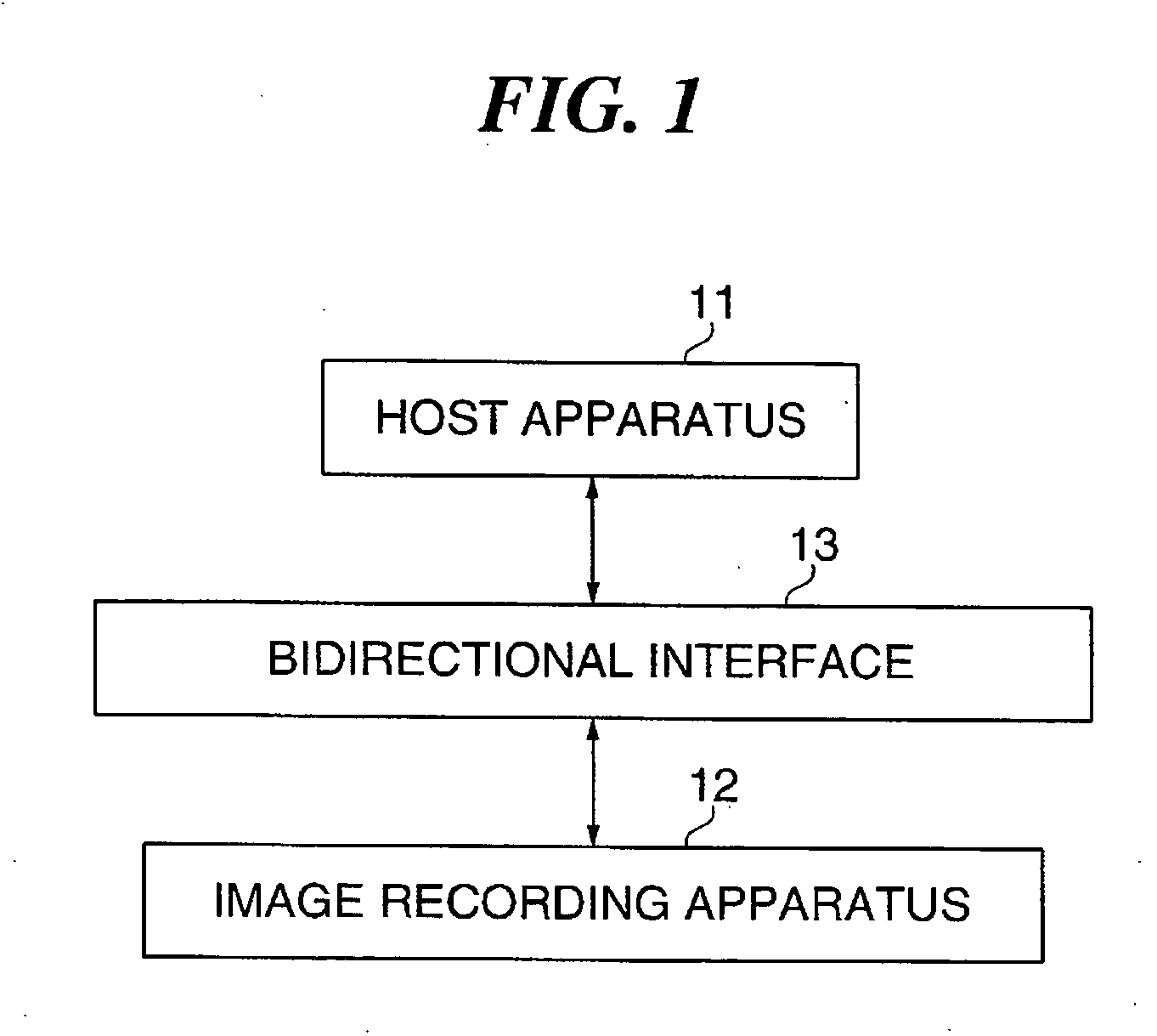
[0063]FIG. 1 is a block diagram schematically showing the construction of the image recording system including the image recording apparatus according to the present embodiment.

[0064] The image recording system shown in FIG. 1 is applied to a directly connectable photo printing system that directly prints image data supplied from a digital camera or the like and that comprises a host apparatus 11 composed of a digital camera or the like, and an image recording apparatus 12 composed of a directly connectable photo printer or the like, with both the appara...


PUM


Abstract

An image recording apparatus that is capable of realizing a favorable print layout where bottom orientations of image data are made uniform easily and at low cost. Rotation information of image data is obtained. A print layout type or pattern in accordance with the rotation information is selected. In accordance with the selected print layout type or pattern, print data for printing a print medium on which the image data is laid out is generated.

Description

BACKGROUND OF THE INVENTION [0001] 1. Field of the Invention [0002] The present invention relates to an image recording apparatus that prints a print medium on which image data is laid out, a method of generating print data for the same, and a control program for implementing the method of generating print data. [0003] 2. Description of the Related Art [0004] Conventionally, when printing image data, a layouter is used for laying out the image data on print media such as sheets. To prevent sheets from being wasted, the layouter automatically aligns a lengthwise orientation of each piece of the image data with a longitudinal direction of a rectangular region designated in advance on the print medium concerned. When it is necessary to rotate images for the orientation alignment, if a method is used that rotates the images by 90° in the same direction every time, the images will be laid out with no consideration whatsoever as to the “top-bottom orientations” of respective images, and t...

Claims


Application Information

Patent Timeline
Patent Type & Authority Applications(United States)
IPC IPC(8): G06K15/00
CPCH04N1/00132H04N1/00188H04N1/00278H04N1/00957H04N2101/00H04N2201/0041H04N2201/33335
Inventor IMAFUKU, KAZUYAHIBI, MAKOTONAITO, HISATSUGUKAWANABE, TETSUYASHIMURA, NORIOMIYAGI, ARATA
Owner CANON KK
Learn More