Linear guiding mechanism

a guiding mechanism and linear technology, applied in optics, instruments, electrical equipment, etc., can solve the problems of increasing the overall production cost the higher procurement cost of the metal rod, etc., and achieve the effect of reducing the overall size of the platform scanner, facilitating assembly, and reducing procurement costs

Inactive Publication Date: 2006-06-15
INTELLECTUAL VENTURES I LLC
View PDF5 Cites 40 Cited by
  • Summary
  • Abstract
  • Description
  • Claims
  • Application Information

AI Technical Summary

Benefits of technology

[0009] Accordingly, one object of the present invention is to provide a linear guiding mechanism for a platform scanner capable of driving the carrier chassis of the scanner linearly forward or backward on a horizontal plane when driven by a driving assembly. In addition, the driving assembly occupies a smaller space so that overall size of the platform scanner is reduced. Furthermore, the platform scanner is easier to assemble and uses materials having a lower procurement cost. Ultimately, overall production cost of the platform scanner is greatly reduced.

Problems solved by technology

Since a metallic rod generally has a higher procurement cost, overall production cost of the platform scanner is increased

Method used


Image

  • Linear guiding mechanism
  • Linear guiding mechanism
  • Linear guiding mechanism

Examples


Embodiment Construction

[0019] Reference will now be made in detail to the present preferred embodiments of the invention, examples of which are illustrated in the accompanying drawings. Wherever possible, the same reference numbers are used in the drawings and the description to refer to the same or like parts.

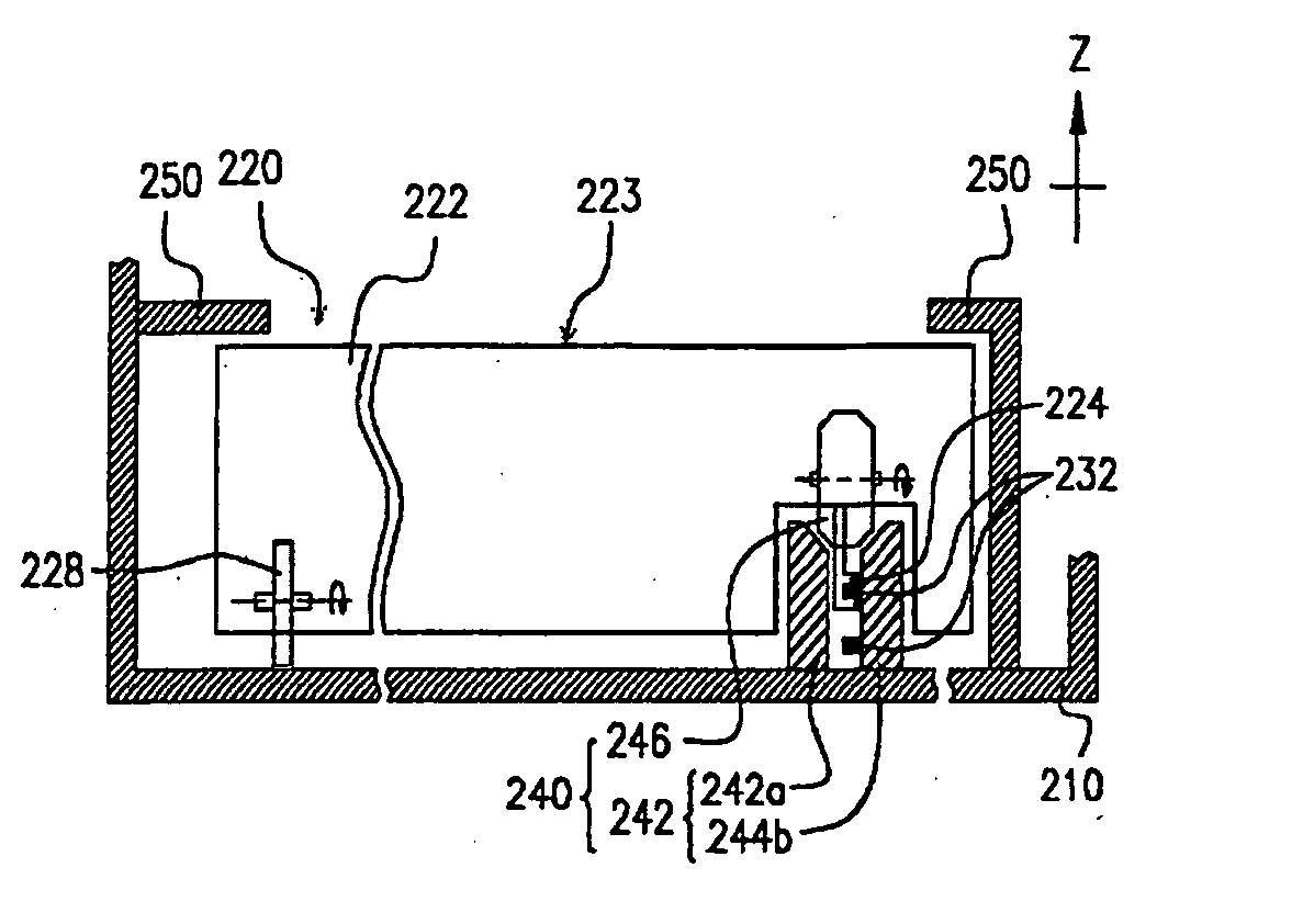
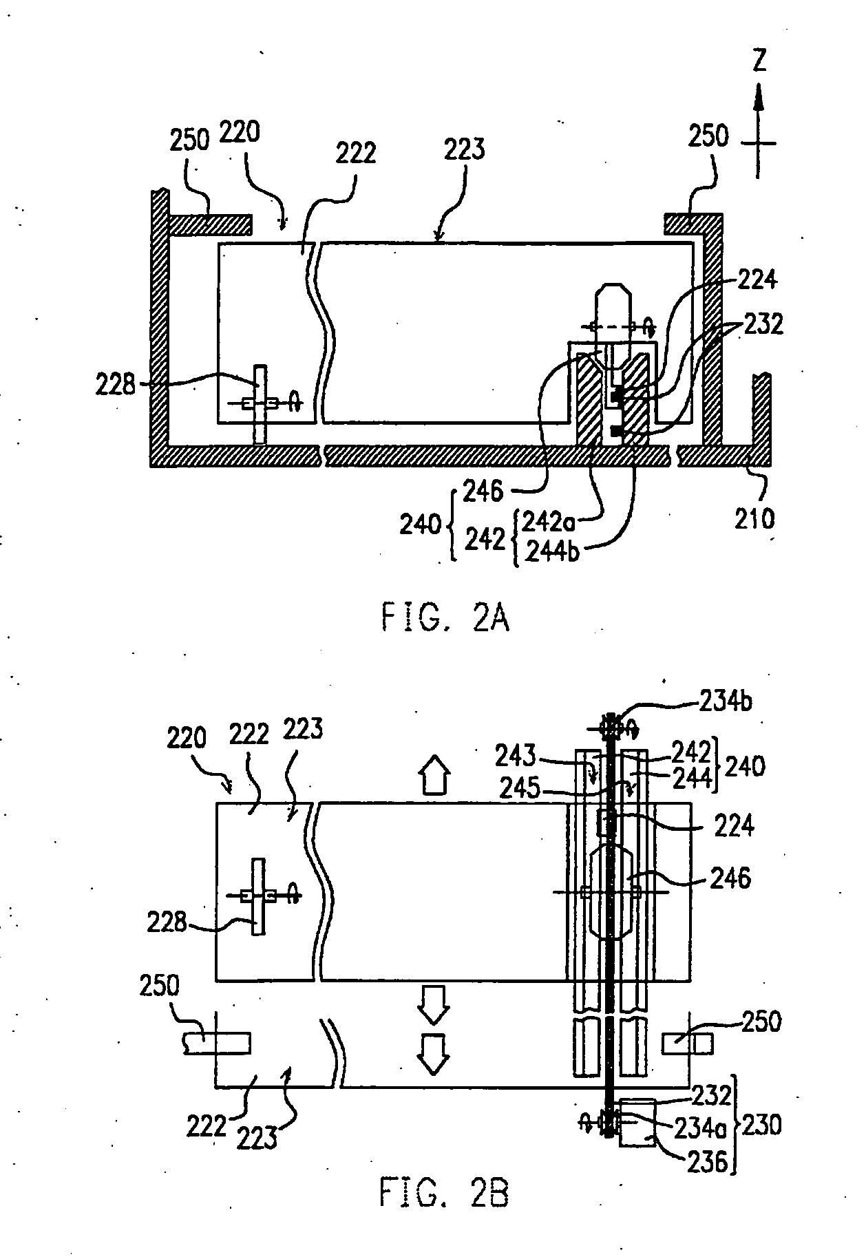
[0020]FIGS. 2A and 2B are the respective front view and top view of a linear guiding mechanism used in one type of platform scanner according to one preferred embodiment of this invention. As shown in FIGS. 2A and 2B, an optical system 220 and a carrier chassis 222 are installed inside the central hollow box-like casing 210 (only a portion is shown) of a platform scanner. To ensure forward and backward movement of the carrier chassis 222 in a horizontal plane along the directions indicated by the arrows so that the optical system 220 may conduct a useful scanning operation, the stepper motor 236 of a driving system 230 rotates a driving wheel 234a directly or indirectly through-a speed reduction de...


PUM


Abstract

A linear guiding mechanism for a platform type optical scanner. A V-shaped track is installed inside a casing and positioned parallel to the travel path of a carrier chassis containing a system of optical devices. The upper section of the V-shaped track has a pair of support surfaces forming an included angle. The V-shaped track supports a positioning wheel or a positioning bump attached to the carrier chassis. The carrier chassis moves along the longitudinal direction of the V-shaped track when driven by a driving system. The V-shaped track may be constructed from a pair of monorails so that the driving belt may move inside the space between the monorails. An additional positioning structure may attach to the interior sidewall of the casing to serve as a retainer for the chassis in an intial position.

Description

BACKGROUND OF INVENTION [0001] 1. Field of Invention [0002] The present invention relates to a linear guiding mechanism. More particularly, the present invention relates to a linear guiding mechanism for guiding horizontal movement of the carrier chassis of an optical scanner. [0003] 2. Description of Related Art [0004] As computing power, network and multi-media technologies continue to improve, the optical scanner has become an indispensable piece of equipment for capturing text or picture images and converting them into a digital image file. Maturity of techniques for fabricating the optical scanner also brings about widespread use alongside a personal computer. At present, the most common type of optical scanner is the platform scanner. In general, a platform scanner includes a transparent flat panel for-placing a document or image to be scanned. Through an internal optical system inside the scanner, the analogue image on the document or image is scanned to produce corresponding...

Claims


Application Information

Patent Timeline
Patent Type & Authority Applications(United States)
IPC IPC(8): H04N1/04G02B27/02H04N1/10
CPCH04N1/1008
Inventor TSENG, JEN-SHOUHSU, HSIU-O
Owner INTELLECTUAL VENTURES I LLC
Why Eureka
Try Eureka