Robust mode staggercasting user controlled switching modes

a user-controlled, robust technology, applied in the direction of data switching networks, television signal transmission by single/parallax channels, pulse modulation television signal transmission, etc., can solve the problem that the component signals, representing higher quality portions of the content representative signal, may become unavailable, etc., to achieve the effect of reducing quality, prolonging delay, and increasing the quality of the component signal

Active Publication Date: 2006-06-15
INTERDIGITAL CE PATENT HLDG
View PDF51 Cites 32 Cited by
  • Summary
  • Abstract
  • Description
  • Claims
  • Application Information

AI Technical Summary

Problems solved by technology

When channel conditions deteriorate, some of the component signals, representing higher quality portions of the content representative signal, may become unavailable.

Method used


Image

  • Robust mode staggercasting user controlled switching modes
  • Robust mode staggercasting user controlled switching modes
  • Robust mode staggercasting user controlled switching modes

Examples


Embodiment Construction

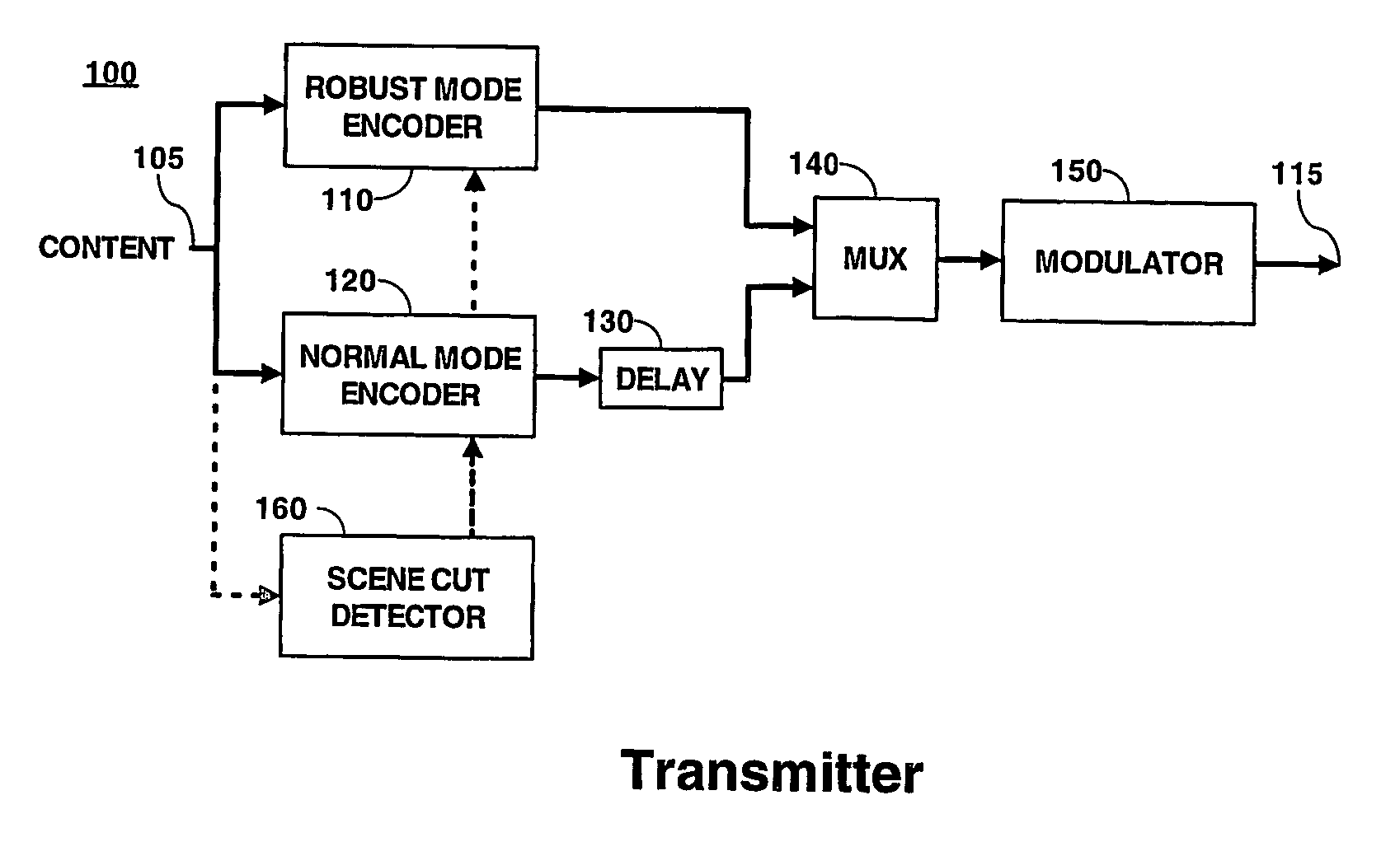
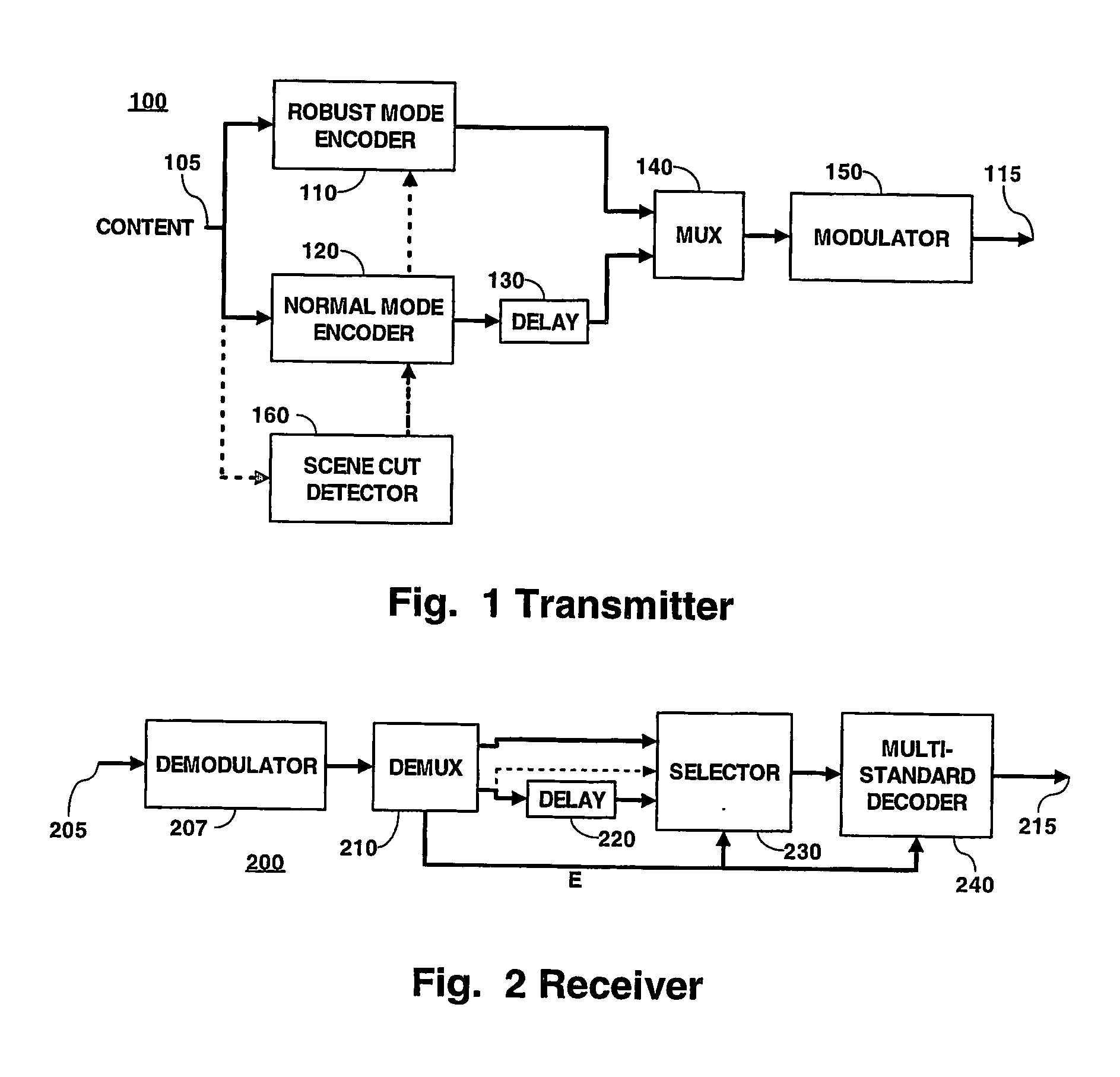
[0025]FIG. 1 is a block diagram of a portion of a staggercasting transmitter 100 according to principles of the present invention. One skilled in the art will understand that other elements, not shown to simplify the figure, are needed for a complete transmitter. One skilled in the art will further understand what those elements are and how to select, design, implement and interconnect those other elements with the illustrated elements.

[0026] In FIG. 1, a source (not shown) of content, which in the illustrated embodiment may be a video image signal, audio sound image, program data, or any combination of these, provides a content representative signal to an input terminal 105 of the transmitter 100. The input terminal 105 is coupled to respective input terminals of a robust mode encoder 110 and a normal mode encoder 120. An output terminal of the robust mode encoder 110 is coupled to a first input terminal of a multiplexer 140. An output terminal of the normal mode encoder 120 is co...


PUM


Abstract

A method and apparatus for staggercasting includes encoding a set of signals representing content. The set of encoded signals is capable of being decoded to produce a corresponding set of decoded signals, each having a quality which is different from the qualities of the decoded signals corresponding to the other encoded signals. A composite signal is generated which includes the set of encoded signals, staggered in time. The set of encoded signals extracting from the composite signal. Errors in the set of extracted encoded signals are detected to produce a subset of available extracted encoded signals which are not erroneous. A content representative signal at a selectable desired quality is then decoded.

Description

[0001] The present patent application claims priority from provisional patent application No. 60 / 443,672 filed on Jan. 28, 2003.BACKGROUND OF THE INVENTION [0002] 1. Field of the Invention [0003] The present invention relates to staggercasting methods and apparatus. [0004] 2. Background of the Invention [0005] Current digital television transmission standards in the United States, as proposed by the Advanced Television Systems Committee (ATSC) dated Sep. 16, 1995, incorporated by reference herein, use a single carrier modulation technique: eight level vestigial sideband modulation (8-VSB). Because it is a single carrier modulation technique, it is susceptible to signal degradation in the communications channel, such as fading caused by multipath and other signal attenuation. While some such fading may be compensated by channel equalization techniques, if the fade is long enough and severe enough, then the receiver will lose the signal and the demodulator system will lose synchroniza...

Claims


Application Information

Patent Timeline
Patent Type & Authority Applications(United States)
IPC IPC(8): H04N11/04H04N11/02H04N7/12H04B1/66H03MH03M1/00H04LH04L1/00H04L27/02H04NH04N1/00H04N1/409H04N1/58H04N7/24H04N7/26H04N7/50H04N7/66H04N19/89H04N19/895H04N21/2383H04N21/438
CPCH04L1/02H04N19/188H04L27/02H04L2001/0098H04N21/234327H04N21/234363H04N21/2362H04N21/2365H04N21/2383H04N21/26275H04N21/4347H04N21/4382H04N21/4383H04N21/631H04N19/172H04N19/169H04N19/61H04N19/107H04N19/12H04N19/142H04N19/164H04N19/39H04N19/895H04L1/08
Inventor BOYCE, JILL MACDONALDRAMASWAMY, KUMARCOOPER, JEFFREY ALLEN
Owner INTERDIGITAL CE PATENT HLDG
Why Eureka
Try Eureka