Robust mode staggercasting without artifacts

a technology of artifacts and robust mode, applied in the field of staggercasting methods and apparatus, can solve the problems of receiver loss of signal, loss of synchronization of demodulator system, and inability to detect the signal in the communication channel,

Inactive Publication Date: 2006-06-15
INTERDIGITAL CE PATENT HLDG
View PDF54 Cites 35 Cited by
  • Summary
  • Abstract
  • Description
  • Claims
  • Application Information

AI Technical Summary

Benefits of technology

[0011] In accordance with principles of the present invention, a method for staggercasting, includes encoding a first signal representing content using source encoding having successive independent decoding segments and encoding a second signal representing the content using source encoding having successive independent decoding segments respectively corresponding to the independent decoding segments of the first encoded signal. A composite signal including the first and second encoded signals is generated in which the first encoded signal is delayed with respect to the second encoded signal. If an error is detected in the composite signal during a portion of an independent decoding segment of the delayed first encoded signal, then the corresponding independent decoding segment of the received second encoded signal is decoded to produce the content, otherwise, the received delayed first encoded signal is decoded to produce the content.

Problems solved by technology

Because it is a single carrier modulation technique, it is susceptible to signal degradation in the communications channel, such as fading caused by multipath and other signal attenuation.
While some such fading may be compensated by channel equalization techniques, if the fade is long enough and severe enough, then the receiver will lose the signal and the demodulator system will lose synchronization.
Reacquiring the signal, and resynchronizing the demodulator can take several seconds and is quite objectionable to a viewer.
However, should one of the component content representative signals have different video characteristics than the other one of the component content representative signals, then switching from one to the other may result in an abrupt visible change in the characteristics of the displayed video image, which may be objectionable to a viewer.
It is not possible to source decode a partial segment.
Thus, it will be impossible to source decode either the partially received segment switched from or the partially received segment switched to.
The video signal source decoded from the received coded signal will be disrupted in a manner which will be visible and objectionable to a viewer.

Method used


Image

  • Robust mode staggercasting without artifacts
  • Robust mode staggercasting without artifacts
  • Robust mode staggercasting without artifacts

Examples


Embodiment Construction

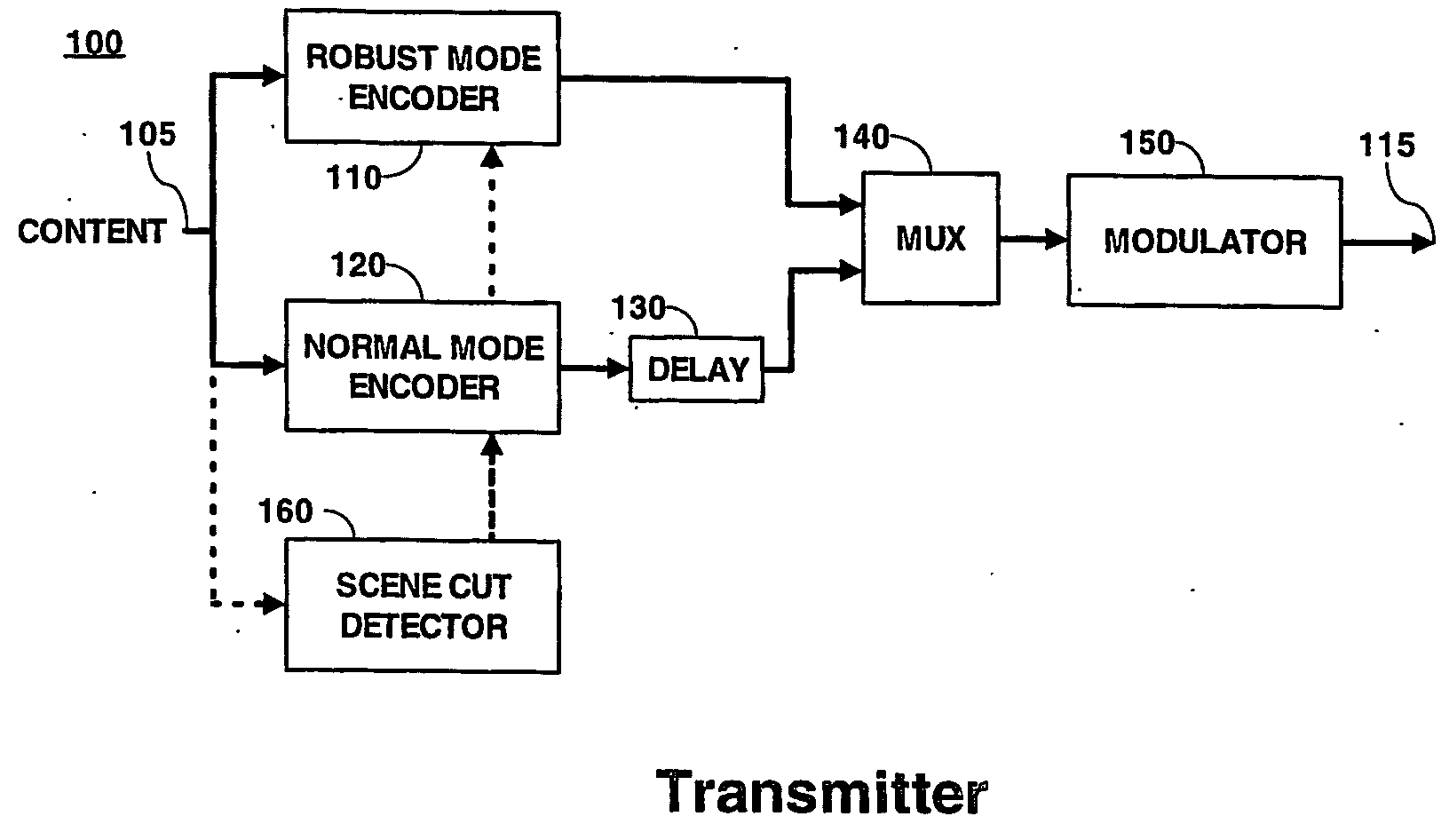
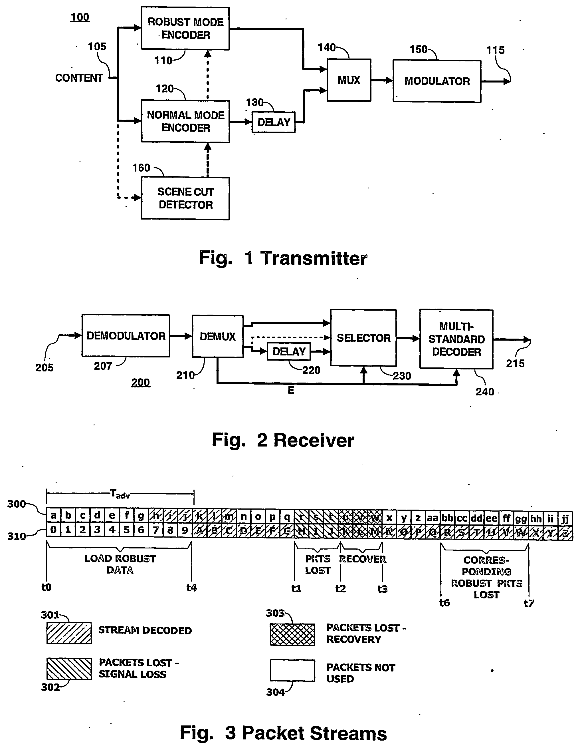
[0025]FIG. 1 is a block diagram of a portion of a staggercasting transmitter 100 according to principles of the present invention. One skilled in the art will understand that other elements, not shown to simplify the figure, are needed for a complete transmitter. One skilled in the art will further understand what those elements are and how to select, design, implement and interconnect those other elements with the illustrated elements.

[0026] In FIG. 1, a source (not shown) of content, which in the illustrated embodiment may be a video image signal, audio sound image, program data, or any combination of these, provides a content representative signal to an input terminal 105 of the transmitter 100. The input terminal 105 is coupled to respective input terminals of a robust mode encoder 110 and a normal mode encoder 120. An output terminal of the robust mode encoder 110 is coupled to a first input terminal of a multiplexer 140. An output terminal of the normal mode encoder 120 is co...


PUM


Abstract

A method for staggercasting, includes encoding a first signal representing content using encoding having successive independent decoding segments and encoding a second signal representing the content using encoding having successive independent decoding segments respectively corresponding to the independent decoding segments of the first encoded signal. A composite signal including the first and second encoded signals is generated in which the first encoded signal is delayed with respect to the second encoded signal. If an error is detected in the composite signal during a portion of an independent decoding segment of the delayed first encoded signal, then the corresponding independent decoding segment of the received second encoded signal is decoded to produce the content, otherwise, the received delayed first encoded signal is decoded to produce the content.

Description

[0001] The present patent application claims priority from provisional patent application No. 60 / 443,672 filed on Jan. 28, 2003.BACKGROUND OF THE INVENTION [0002] 1. Field of the Invention [0003] The present invention relates to staggercasting methods and apparatus. [0004] 2. Background of the Invention [0005] Current digital television transmission standards in the United States, as proposed by the Advanced Television Systems Committee (ATSC) dated Sep. 16, 1995, incorporated by reference herein, use a single carrier modulation technique: eight level vestigial sideband modulation (8-VSB). Because it is a single carrier modulation technique, it is susceptible to signal degradation in the communications channel, such as fading caused by multipath and other signal attenuation. While some such fading may be compensated by channel equalization techniques, if the fade is long enough and severe enough, then the receiver will lose the signal and the demodulator system will lose synchroniza...

Claims


Application Information

Patent Timeline
Patent Type & Authority Applications(United States)
IPC IPC(8): H04N7/12H04N11/04H04B1/66H04N11/02H03MH03M1/00H04LH04L1/00H04L27/02H04NH04N1/00H04N1/409H04N1/58H04N7/24H04N7/26H04N7/50H04N7/66H04N19/89H04N19/895H04N21/2383H04N21/438
CPCH04L1/02H04N19/36H04L27/02H04L2001/0098H04N21/234327H04N21/234363H04N21/234381H04N21/2362H04N21/2365H04N21/2383H04N21/2662H04N21/4347H04N21/4382H04N21/4383H04N21/631H04N19/00H04N5/85H04N7/50H04N9/8042H04N19/176H04N19/172H04N19/63H04N19/169H04N19/61H04N19/37H04N19/107H04N19/12H04N19/142H04N19/164H04N19/39H04N19/89H04N19/20H04N19/895H04N19/188H04L1/08H04N1/409H04N1/58H04N7/12
Inventor BOYCE, JILL MACDONALDCOOPER, JEFFREY ALLENRAMASWAMY, KUMAR
Owner INTERDIGITAL CE PATENT HLDG
Why Eureka
Try Eureka