
Database accelerator

a technology of accelerator and database, applied in relational databases, data processing applications, instruments, etc., can solve the problems of inability to achieve greater processing performance, lack of scalability, and upper limit of their performance, and achieve the effect of distributing the load on the database and low cos

Inactive Publication Date: 2006-06-15
ANNEX SYST
View PDF4 Cites 10 Cited by
  • Summary
  • Abstract
  • Description
  • Claims
  • Application Information

AI Technical Summary

Benefits of technology

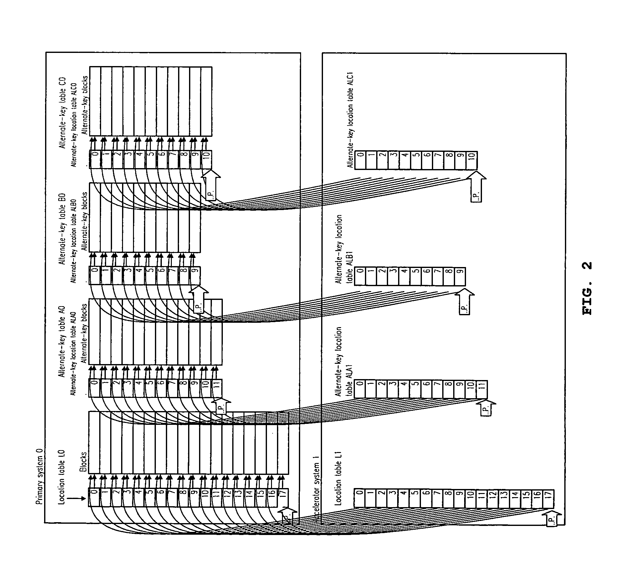
[0045] This shows that the volume of data processed may be increased by deploying multiple location tables and alternate-key location tables, copying their most recent entries and alternate-key entries, increasing the number of paths permitting key retrieval and allocating a CPU to each path.
[0059] It is possible to disperse the load on a database by thus providing an accelerator system or systems and deploying duplicates of the location table and alternate-key location tables. And since an accelerator system does not maintain blocks or alternate-key blocks, it requires only one in several tens to one in several hundreds the data storage capacity of the primary system, and expansion of the system may be achieved at extremely low cost.

Problems solved by technology

In the Data Storage and Retrieval System thus characterized, it is possible to maximize hardware performance and achieve considerable high performance, but it cannot achieve any greater processing performance; in other words, it lacks scalability.
However, since conventional methods are premised on the use of hard disks, although it is possible to achieve acceleration to speeds greater than those achieved with hard disks by employing high-speed memory devices such as semiconductors, the performance limit of those high-speed memory devices then constitutes the upper limit on their performance and so they do not essentially achieve scalability.
However, this approach suffers from a fatal shortcoming.
This is that since multiple servers are capable of processing only the logic of the processing and since a database is a singularity and each server accesses the same database, database performance has been restricted by processing performance.
In other words, ever if servers are added for increases in processing requests, database performance reaches an upper limit.
However, since the secondary system may not be used for updating, the scalability that may thus be achieved is limited.
Further, since a secondary system must be of the same configuration as the primary system and the location table, data-storage files (aggregations of blocks) and (zero, one or multiple) alternate-key tables deployed on it as a set, it has been a large financial burden to deploy multiple secondary systems for the purpose of achieving scalability in addition to the purpose of backup.
Another conventional method not entailing the Data Storage and Retrieval System that is in general use to improve performance is mirroring of servers that hold data, but since a mirror database must be of the same size as the original database, this has required large storage volumes and also entailed great restrictions on updating since a mirror database may basically be used only for referencing the data.
It is restricted by the inability to reflect on a mirror server the updating occasioned by the modification of data on the main server without a certain temporal delay.
This entails the danger that when data is updated on a mirror server, the outcome of updating may be rendered invalid due to the time lag with updating on the main server, and this method is one that cannot be adopted for regular data processing.
Thus, performance improvement using mirror servers may not be employed in regular real-time data processing.
Thus, circumstances are such that the achievement scalability for databases is a significant problem, but an adequate solution does not exist.
These circumstances arise from, in addition to the need to duplicate the data itself, the complexity of index structures in conventional methods that makes duplication troublesome when indices are updated.

Method used


Image

  • Database accelerator
  • Database accelerator
  • Database accelerator

Examples


Embodiment Construction

[0084] The present invention is based on the concepts of the Data Storage and Retrieval System (Japanese Patent 3345628, U.S. Pat. No. 6,415,375 and U.S. Pat. No. 6,584,555) and has the objective of achieving scalability while using the basic elements thereof unmodified.

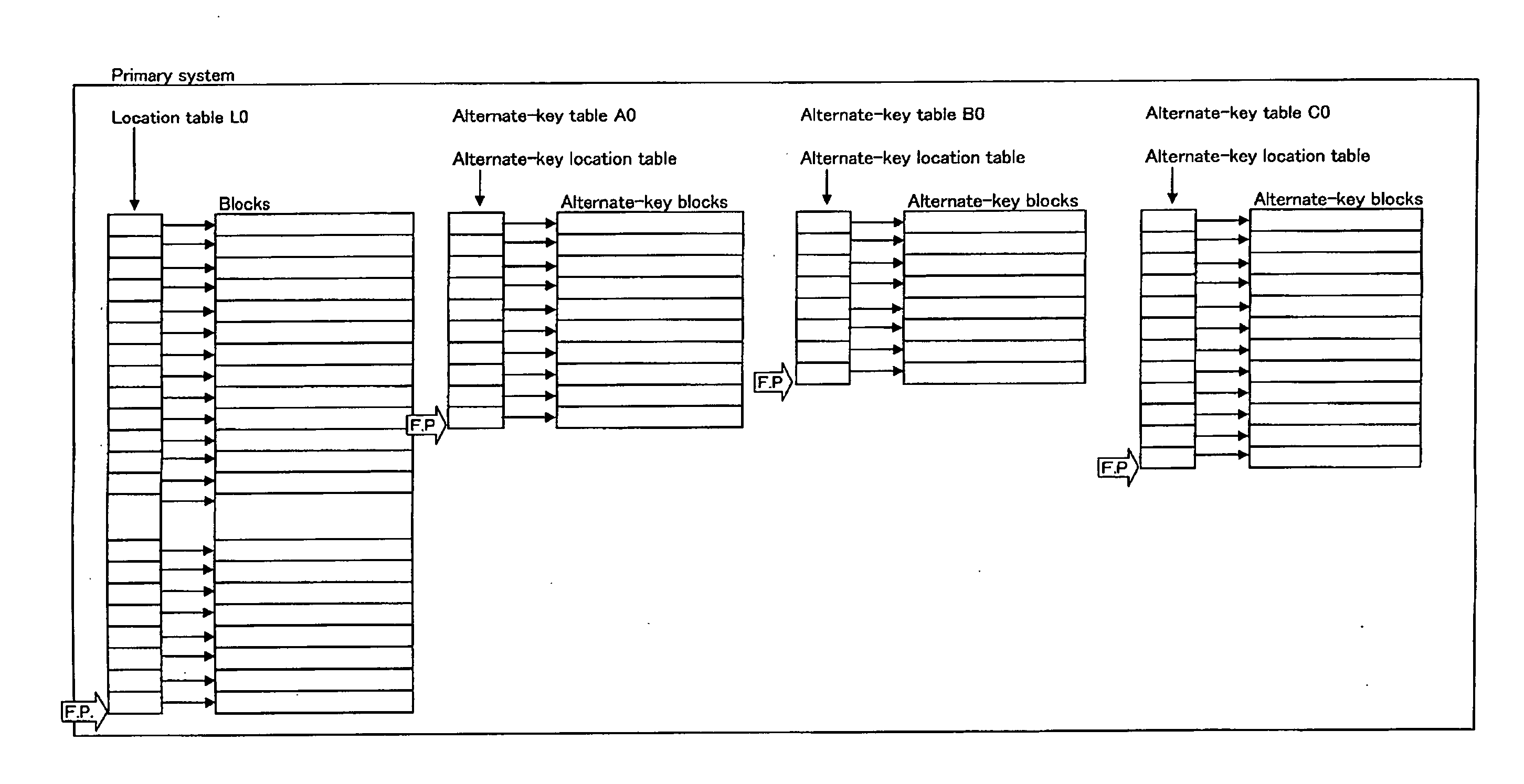
[0085] As a method of achieving scalability, the present invention deploys multiple location tables and alternate-key location tables of the inventions of the Data Storage and Retrieval System and the Database Reorganization System, and implements considerable increases in the overall processing volume by dispersing the load of binary searches performed on those.

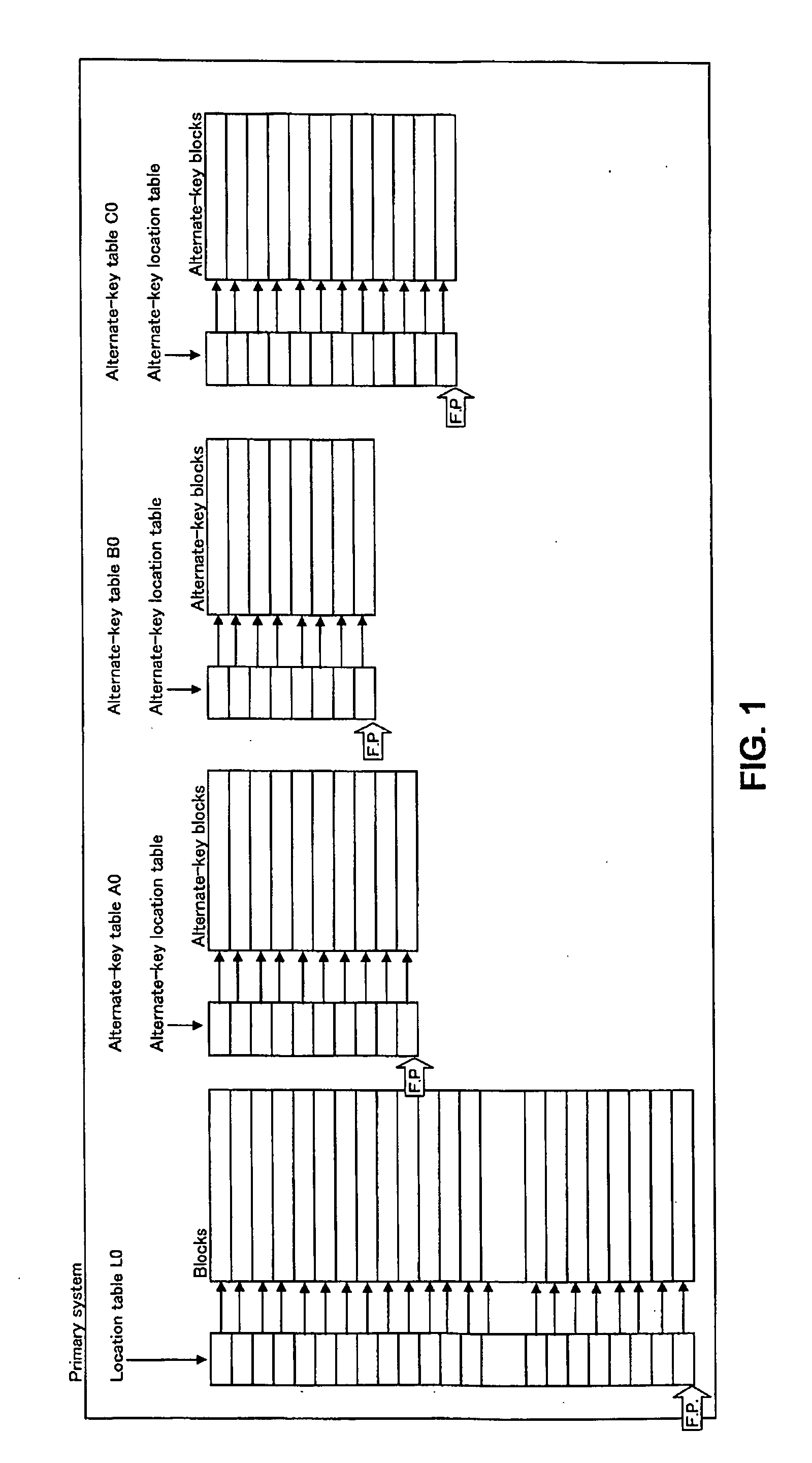
[0086] A set of a location table and its blocks and alternate-key tables (one alternate-key location table and its alternate-key blocks for each alternate key) is termed a primary system. FIG. 1 is an example of a primary system. Three type alternate keys have been created here.

[0087] An accelerator or an accelerator system containing a location table and ...


PUM


Abstract

While scalability in database processing may be achieved gradually and at low cost, to achieve high scalability of several thousand times. This database accelerator holds on an accelerator system copies of location tables, which correspond to primary-key indices, and alternate-key location tables, which correspond to alternate-key indices, for a primary system that performs data updates. When a location table or alternate-key location table on the primary system is modified, updates are synchronized to the location table and alternate-key location tables on the accelerator system. The data itself is held only on the primary system. Major improvements in processing capabilities are achieved over serial processing by distributing processing requests among accelerator systems.

Description

BACKGROUND OF THE INVENTION [0001] 1. Field of the Invention [0002] The invention pertains to data storage and retrieval methods and systems in the field of computers and has the particular objective of achieving high scalability (the expansion of processing capability) in data storage and retrieval. Scalability is the expansion of processing capability. The invention pertains to the improvement of database system performance in providing to a given database system with a certain level of performance processing capability of from several times to several thousand times greater performance. [0003] 2. Description of Related Art [0004] As described in Jeffrey D. Ullman, Deetabeesu Shisutemu no Genri [Principles of Database Systems] (trans. Kunii et al, Nihon Konpyuutaa Kyokai, 25 May 1985, pp. 45-71), Samuel Leffler et al, UNIX 4.3 BSD no Sekkei to Jissou [The Design and Implementation of UNIX 4.3 BSD] (trans. Akira Nakamura et al, Maruzen K. K., 30 Jun. 1991, pp. 193-191) and Michael ...

Claims


Application Information

Patent Timeline
Patent Type & Authority Applications(United States)
IPC IPC(8): G06F7/00G06F12/00G06F17/30
CPCG06F17/30595G06F16/284Y10S707/99932
Inventor TAMATSU, MASAHARU
Owner ANNEX SYST
Learn More