Pallet replacing device

Inactive Publication Date: 2006-06-22
MAKINO MILLING MASCH CO LTD
View PDF9 Cites 14 Cited by
  • Summary
  • Abstract
  • Description
  • Claims
  • Application Information

AI Technical Summary

Benefits of technology

[0012] The pallet support member is arranged at a position in the extension of the table in the horizontal direction perpendicular to the spindle axis, and therefore the pallet moves only linearly. This configuration also makes it possible to reduce the floor space required for the pallet change operation.
[0013] According to the present inven

Problems solved by technology

The conventional pallet changer for holding the pallets in a horizontal position on arms rotatable about a vertical axis or the pallet changers disclosed in International Publication WO01/94071 and U.S. Pat.

Method used


Image

  • Pallet replacing device
  • Pallet replacing device
  • Pallet replacing device

Examples


Example

[0023] Preferred embodiments of the present invention will be described below with reference to the accompanying drawings.

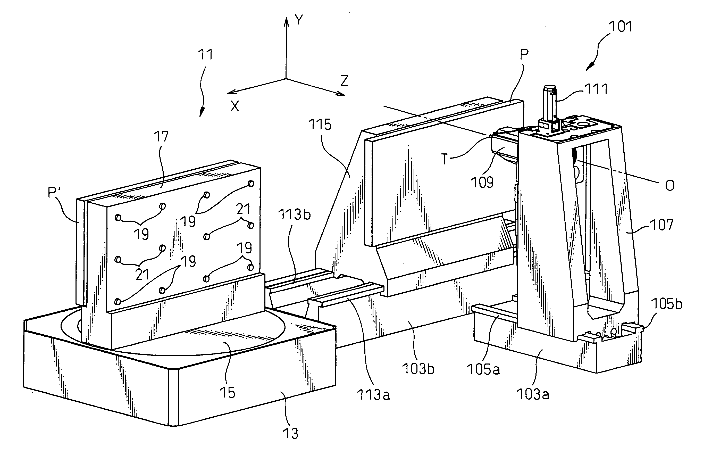
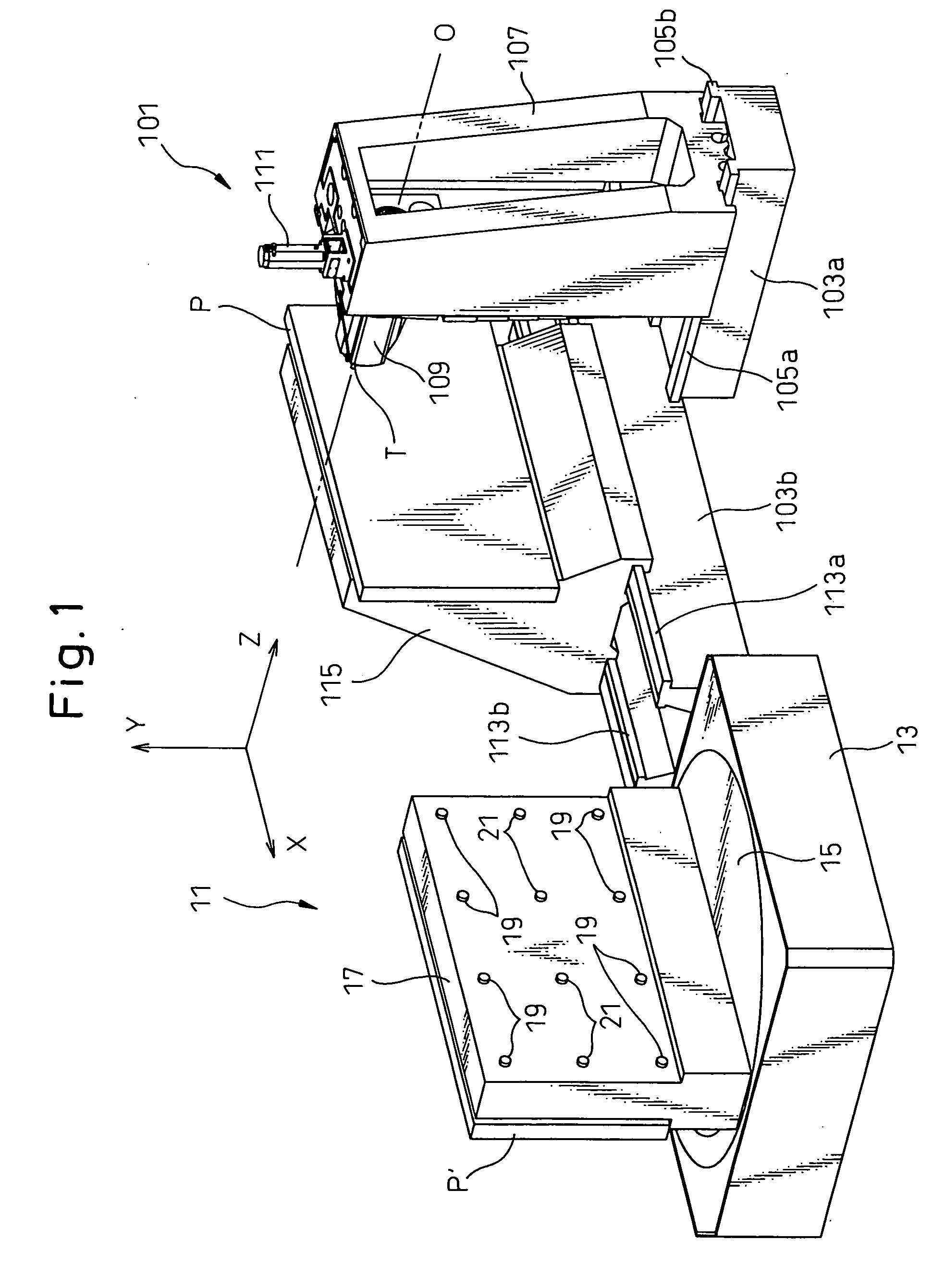
[0024] First, referring to FIG. 1, a pallet changer 11 according to a preferred embodiment of the present invention is arranged adjacent to a machine tool 101 to exchange new and old pallets P and P′ while they are kept in a vertical position. The machine tool 101 includes, as main components, first and second beds 103a, 103b, a column 107 disposed on the first bed 103a, a spindle head 109 disposed on the column 107 for rotatably supporting a spindle (not shown), and a table 115 disposed on the second bed 103b.

[0025] Z-axis guide rails 105a, 105b are disposed on the upper surface of the first bed 103a to extend in parallel to a rotational axis O of the spindle. The column 107 is adapted to move reciprocably along the Z-axis guide rails 105a, 105b. Also, the machine tool 101 has, as a Z-axis feed means, a threaded shaft (not shown) extending along Z-axis in the ...


PUM


Abstract

A pallet P held in a vertical position is moved from a pallet mounting surface, formed to extend vertically on a table 115 of a machine tool 101, to a pallet mounting surface formed vertically on a pallet support member 17 of a pallet changer 11. After rotationally indexing a swivel base 15 by 180 degrees about a vertical axis, a pallet P′ is moved from the pallet support member 17 to the table 115.

Description

TECHNICAL FIELD [0001] The present invention relates to a pallet changer for changing a pallet held in a vertical position on a vertical surface, of a table or a pallet mount of a machine tool, on which the pallet is removably mounted. BACKGROUND ART [0002] A machine tool in which a pallet having a workpiece fixed thereon is mounted removably on the table or the pallet mount of a machine tool to machine the workpiece is widely used. In such a machine tool, a pallet changer is used to replace a machined workpiece with a workpiece yet to be machined. In the conventional pallet changer, new and old pallets are placed on arms extending in opposite horizontal directions on both sides of a rotary shaft extending vertically, and the pallets are replaced by rotating the rotary shaft by 180 degrees and thus exchanging the positions of the new and old pallets. [0003] The pallet changer described above is configured to support the pallets in a horizontal position. However, a pallet changer sup...

Claims


Application Information

Patent Timeline
IPC IPC(8): B23Q39/04B23Q7/00B23Q7/02B23Q7/14
CPCB23Q7/02Y10T29/5124B23Q7/1431
Inventor KIKUCHI, NORIYUKI
Owner MAKINO MILLING MASCH CO LTD
Why Eureka
Try Eureka