Support moment control method for leg motion support orthosis

a technology of support orthosis and moment control, which is applied in the field of support moment control of leg motion support orthosis, can solve the problems of jerky leg motion, disadvantageous leg motion, and inability to make a smooth leg motion, and achieve the effect of reducing the force applied

Inactive Publication Date: 2006-06-22
HONDA MOTOR CO LTD
View PDF4 Cites 62 Cited by
  • Summary
  • Abstract
  • Description
  • Claims
  • Application Information

AI Technical Summary

Benefits of technology

[0008] In view of the above background, the present invention has been provided. Therefore, it is an object of the present invention to provide a support moment control method for a leg motion support orthosis capable of effectively reducing forces applied to a person other than forces necessary to support the person's leg motion, such as the weight of the leg motion support orthosis put on the person and thereby enabling the person to feel like

Problems solved by technology

Consequently, the support orthosis is susceptible to a difference between the actual leg motion pattern and the motion pattern supposed by the person.
Furthermore, it leads to causing a jerky leg motion or to making it hard to make a smooth leg motion disadvantageously.
Moreover, since the support orthosis of the patent document 1 has a lot of force sensors provided on the bottom face of the each foot support portion and on the bands fixed to the person's leg, it is disadvantageous in cost and has a problem that it is susceptible to noise

Method used


Image

  • Support moment control method for leg motion support orthosis
  • Support moment control method for leg motion support orthosis
  • Support moment control method for leg motion support orthosis

Examples


Embodiment Construction

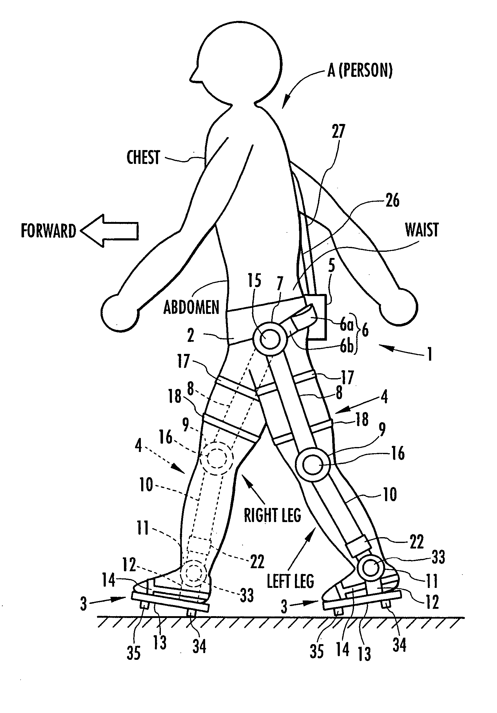
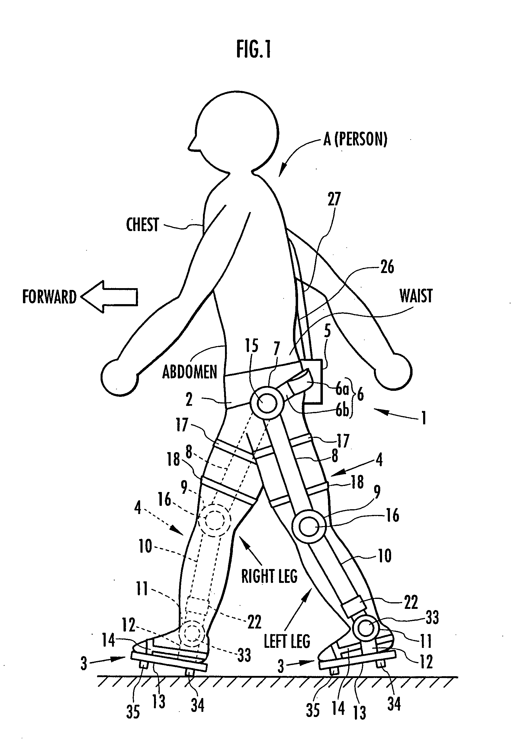
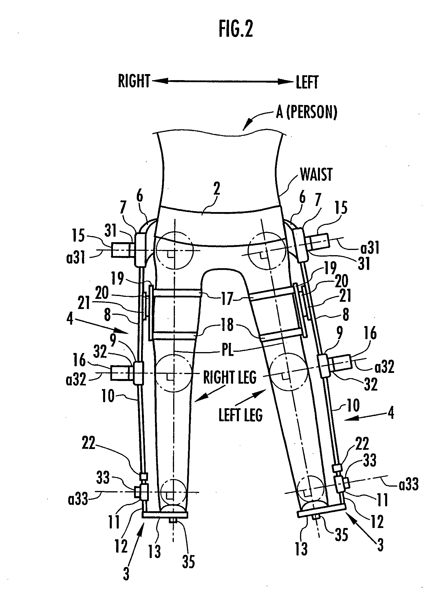
[0056] One embodiment of the present invention will now be described by referring to FIG. 1 to FIG. 26. FIG. 1 shows a state in which a leg motion support orthosis 1 according to this embodiment is put on a person A in the form of a side view. FIG. 2 shows the lower part of the body of the person A wearing the leg motion support orthosis 1 in the form of a front view. In FIG. 2, the hip joint, the knee joint, and the ankle joint of each leg of the person A are each represented by a chain-line circle for convenience of explanation.

[0057] In FIG. 1 and FIG. 2, the leg motion support orthosis 1 (hereinafter, simply referred to as the support orthosis 1) includes a waist attachment portion 2 fixed to the waist of the person A, a pair of right and left foot attachment portions 3, 3 fixed to the foot portions of the right and left legs of the person A, respectively, and a pair of right and left leg link portions 4, 4 for coupling the waist attachment portion 2 to the right and left foot ...


PUM


Abstract

Target joint support moments of each leg are determined by estimating joint moments of the each leg necessary for the person A wearing a leg motion support orthosis (1) to make a motion independently and according to the estimated joint moments. Moreover, floor reaction forces for the support orthosis (1) to make a motion independently are estimated, and then estimated values of actual joint support moments actually applied from the support orthosis (1) to the joints of the each leg of the person (A) are found by using the estimated floor reaction forces and outputs of the force sensor (22) provided in a leg link portion (4) of the support orthosis (1). Torque generation units (15) and (16) of the support orthosis (1) are controlled in such a way that the estimated values of the actual joint support moments are coincident with the target joint support moments. Thereby, the leg motion of the person can be supported. Moreover, it effectively prevents forces other than the necessary forces to support the leg motion of the person from acting on the person and enables the person to make a leg motion with feeling as if the person were not wearing the leg motion support orthosis as fully as possible.

Description

BACKGROUND OF THE INVENTION [0001] 1. Field of the Invention [0002] The present invention relates to a support moment control method for a leg motion support orthosis put on a person to support the motion (walking or the like) of his or her legs. [0003] 2. Related Background Art [0004] Conventionally, there is an already known leg motion support orthosis disclosed in Japanese Patent Laid-Open No. 2003-220102 (hereinafter, referred to as “patent document 1”) as this type of leg motion support orthosis. In the support orthosis in the patent document 1, a waist support belt to be put on a person's waist is coupled to each foot support portion where the person's foot portion is placed, via a waist moment generator corresponding to a hip joint, a thigh support beam corresponding to a thigh, a knee moment generator corresponding to a knee joint, a shank support beam corresponding to a crus portion, and a heel moment generating section corresponding to an ankle joint in this order from the...

Claims


Application Information

Patent Timeline
IPC IPC(8): A61F5/00
CPCA61F5/0102
Inventor IKEUCHI, YASUSHI
Owner HONDA MOTOR CO LTD
Why Eureka
Try Eureka