Driving an electrophoretic display

a technology of electrophoretic display and drive circuit, which is applied in the direction of static indicating devices, non-linear optics, instruments, etc., can solve the problem of insufficient ability of said particles to reach the other extreme position, and achieve the effect of improving the reproduction quality of pictures and being easy to mov

Inactive Publication Date: 2006-06-22
KONINKLIJKE PHILIPS ELECTRONICS NV
View PDF9 Cites 67 Cited by
  • Summary
  • Abstract
  • Description
  • Claims
  • Application Information

AI Technical Summary

Benefits of technology

[0048] In an embodiment in accordance with the invention as claimed in claim 13, both first and second shaking pulses are generated. The first shaking pulse is present for all pixels during the same first shaking period which precedes the reset period in which the reset pulse is applied. The second shaking pulse is present for all pixels during the same second shaking period which precedes the drive period during which the drive pulse is applied. This second shaking pulse further improves the reproduction quality of the picture to be displayed.
[0049] In an embodiment in accordance with the invention as claimed in claim 14, an over-reset is used wherein the duration of the reset pu

Problems solved by technology

Each level (which is one preset pulse) of the shaking pulse has an energy (or a duration if the voltage level is fixed) sufficient to release

Method used


Image

  • Driving an electrophoretic display
  • Driving an electrophoretic display
  • Driving an electrophoretic display

Examples


Embodiment Construction

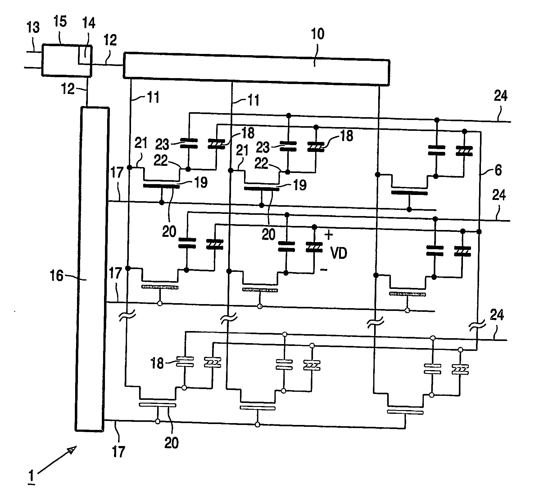
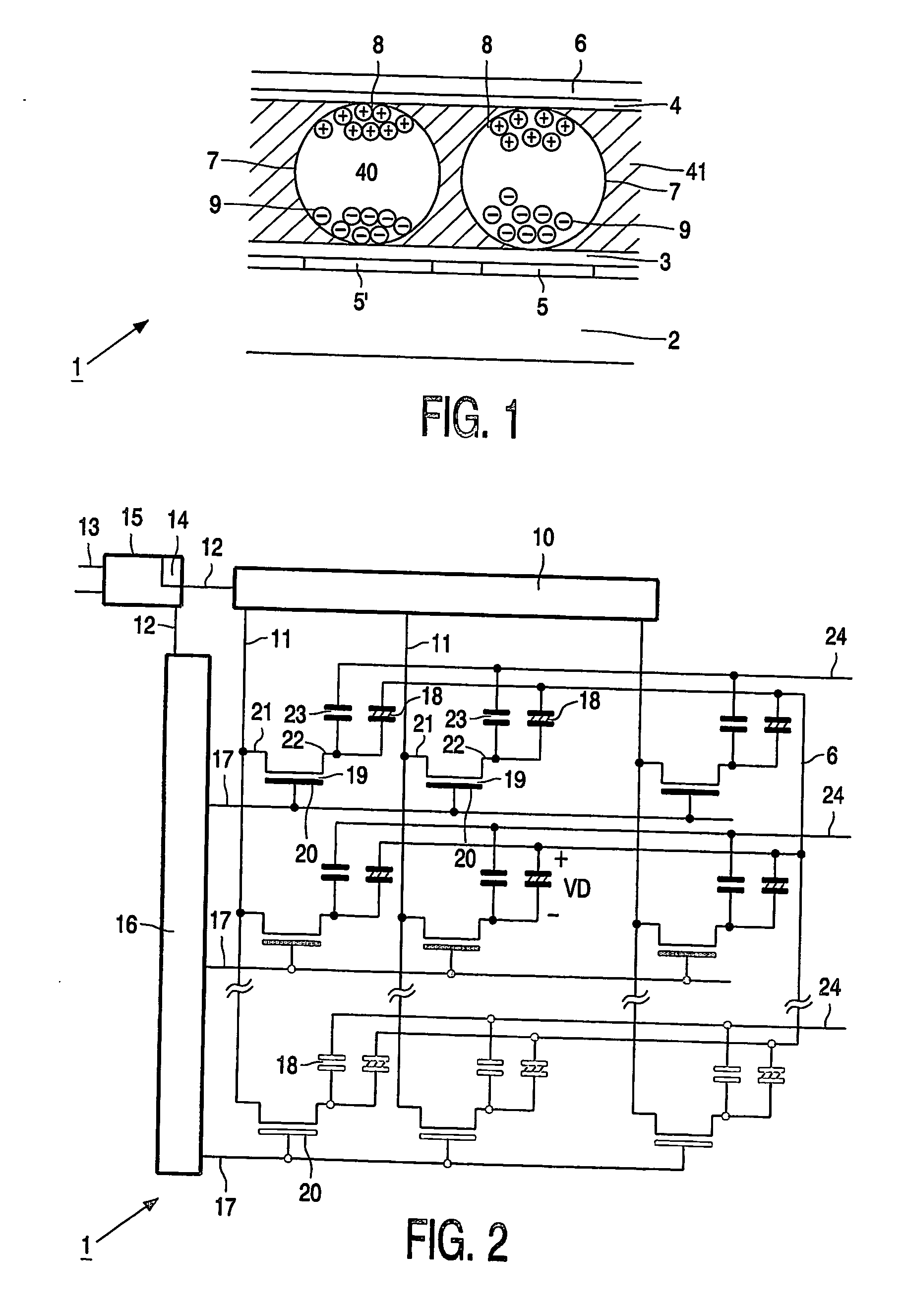
[0065]FIG. 1 shows diagrammatically a cross-section of a portion of an electrophoretic display, which for example, to increase clarity, has the size of a few display elements only. The electrophoretic display comprises a base substrate 2, an electrophoretic film with an electronic ink which is present between two transparent substrates 3 and 4 which, for example, are of polyethylene. One of the substrates 3 is provided with transparent pixel electrodes 5, 5′ and the other substrate 4 with a transparent counter electrode 6. The counter electrode 6 may also be segmented. The electronic ink comprises multiple microcapsules 7 of about 10 to 50 microns. Each microcapsule 7 comprises positively charged white particles 8 and negatively charged black particles 9 suspended in a fluid 40. The dashed material 41 is a polymer binder. The layer 3 is not necessary, or could be a glue layer. When the pixel voltage VD across the pixel 18 (see FIG. 2) is supplied as a positive drive voltage Vdr (see...


PUM


Abstract

A drive circuit for an electrophoretic matrix display comprises a select driver (16) for selecting lines of pixels (18) of the matrix display. A data driver (10) supplies drive voltage waveforms (VD) to each one of the selected pixels (18) via data electrodes (5, 5′). A controller (15) controls the select driver (16) to select a group of lines of pixels (18) at a same time during portions of the drive voltage waveforms (VD) which for each of the data electrodes (5, 5′) are equal for at least all the pixels (18) which are associated with the same one of the data electrodes (5, 5′).

Description

FIELD OF THE INVENTION [0001] The invention relates to a drive circuit for an electrophoretic display, an electrophoretic display, a display apparatus comprising such an electrophoretic display, and a method of driving an electrophoretic display. [0002] Electrophoretic displays are used in, for example, electronic books, mobile telephones, personal digital assistants, laptop computers, and monitors. BACKGROUND OF THE INVENTION [0003] A display device of the type mentioned in the opening paragraph is known from international patent application WO 99 / 53373. This patent application discloses an electronic ink display which comprises two substrates, one of which is transparent, the other substrate is provided with electrodes arranged in rows and columns. Display elements or pixels are associated with intersections of the row and column electrodes. Each display element is coupled to the column electrode via a main electrode of a thin-film transistor (further referred to as TFT). A gate o...

Claims


Application Information

Patent Timeline
IPC IPC(8): G09G3/34G02F1/167G02F1/16757G09G3/20G09G3/38
CPCG02F1/167G09G3/34G09G2300/08G09G2310/0205G09G2330/021G09G2310/061G09G2310/068G09G2320/04G09G2310/06G02F1/16757G02F1/1685G09G3/344
Inventor JOHNSON, MARK THOMAS
Owner KONINKLIJKE PHILIPS ELECTRONICS NV
Why Eureka
Try Eureka