
Technique for image data recording

a technology of image data and recording, applied in the field of image data recording, can solve the problems of affecting the speed of image display, reducing the picture quality of displayed images, and extending the time required for data supply, so as to achieve the effect of prompt image display

Inactive Publication Date: 2006-06-22
SEIKO EPSON CORP
View PDF5 Cites 6 Cited by
  • Summary
  • Abstract
  • Description
  • Claims
  • Application Information

AI Technical Summary

Benefits of technology

[0006] In view of the drawbacks of the prior art techniques, the object of the invention is to provide a technique of accelerating supply of control data of dot formation to an image display device and thereby attaining prompt image display.

Problems solved by technology

Size expansion of individual pixels naturally expands the size of a displayed image, but undesirably lowers the picture quality of the displayed image.
These measures to the better-quality demand and the size expansion demand of the displayed image, however, hinder quick image display.
The increase in number of pixels included in one image thus undesirably extends the time required for data supply and interferes with prompt image display.

Method used


Image

  • Technique for image data recording
  • Technique for image data recording
  • Technique for image data recording

Examples


first embodiment

B. First Embodiment

[0085] B-1. System Configuration

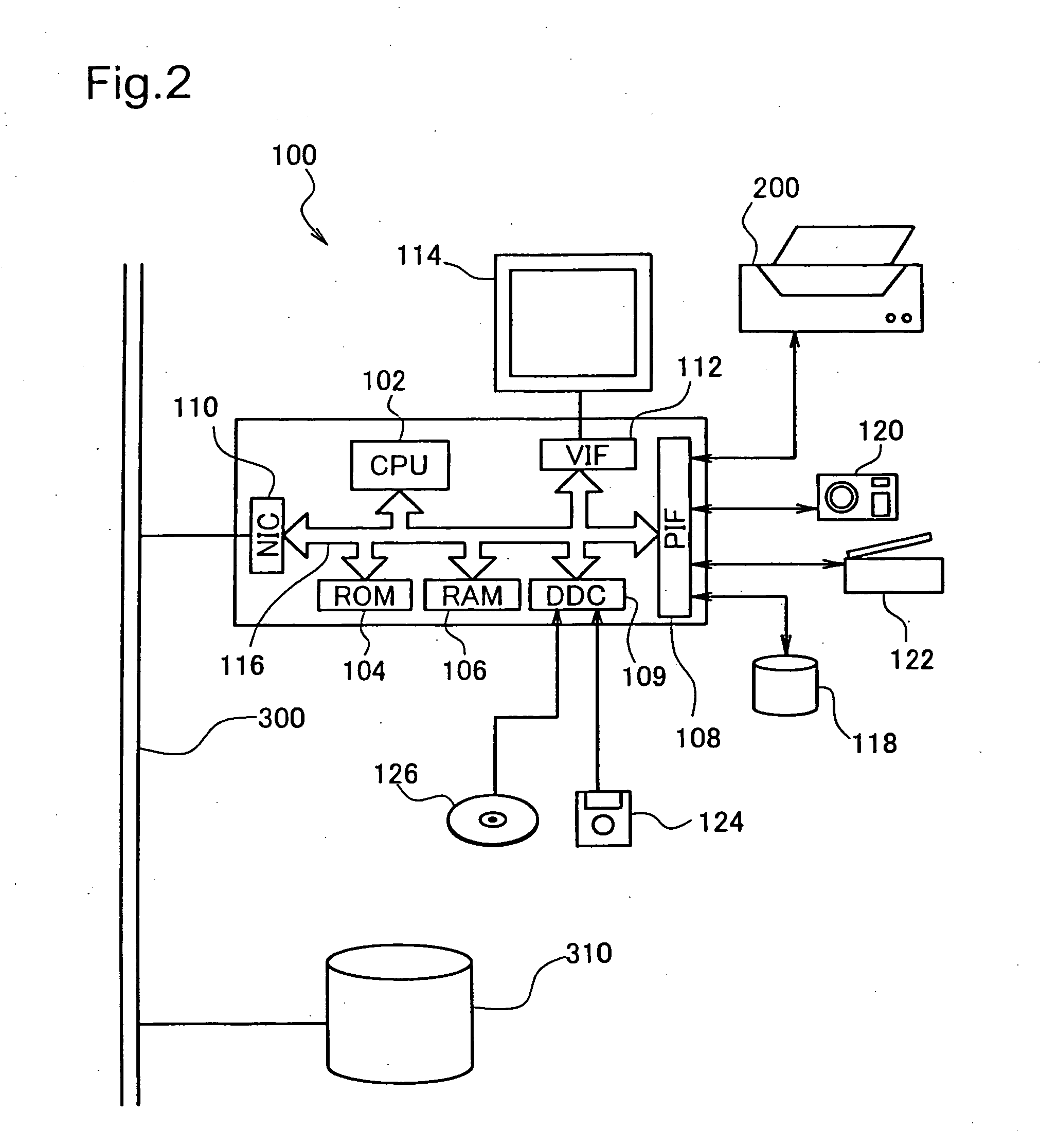
[0086]FIG. 2 illustrates the configuration of a computer 100 as an image processing device in a first embodiment. The computer 100 is a known computer including a CPU 102, a ROM 104, and a RAM 106 interconnected via a bus 116.

[0087] The computer 100 has a disk controller DDC 109 to read data from, for example, a flexible disk 124 or a compact disc 126, a peripheral equipment interface PIF 108 to receive and send data from and to peripheral equipment, and a video interface VIF 112 to drive and actuate a CRT 114. The PIF 108 is connected with a color printer 200 described later and a hard disk unit 118. Connection of a digital camera 120 or a color scanner 122 with the PIF 108 enables printing of images taken by the digital camera 120 or the color scanner 122. Insertion of a network interface card NIC 110 to the computer 100 causes the computer 100 to connect with a communication line 300 and obtain data stored in a storage device 3...

second embodiment

C. Second Embodiment

[0148] The procedure of the first embodiment discussed above divides one pixel into multiple smaller pixels and gathers the multiple smaller pixels as divisions of an identical original pixel to a pixel group. Division of one pixel into multiple smaller pixels is required, for example, when an image is printed at a higher resolution than the resolution of input image data. In the procedure of the first embodiment, the respective pixels included in one pixel group have an identical tone value. The technique of the invention is, however, also applicable to a pixel group of multiple pixels having different tone values. For example, when the printing resolution is set identical with the resolution of the input image data and one pixel group includes multiple pixels of image data, the multiple pixels included in the pixel group may have different tone values. In another example, when additional pixels are newly created for printing an image at a higher resolution than...

third embodiment

D. Third Embodiment

[0170] In the first and the second embodiments discussed above, each pixel takes only either of the two tone values corresponding to the dot-on state and the dot-off state. Some printers may, however, be capable of varying the size of dots or varying the density of ink used for dot creation to express a greater number of tone values in individual pixels. The technique of the invention is effectively applicable to such multi-valued printers. Application of the technique of the invention to a multi-valued printer is described below as a third embodiment.

[0171] D-1. Schema of Image Printing Process

[0172]FIG. 20 is a flowchart showing an image printing process executed in the third embodiment. The primary difference of the image printing process of the third embodiment from the image printing process of the first embodiment discussed above with reference to FIG. 5 is conversion of color-converted data into large-size, medium-size, and small-size dot data. The image ...


PUM


Abstract

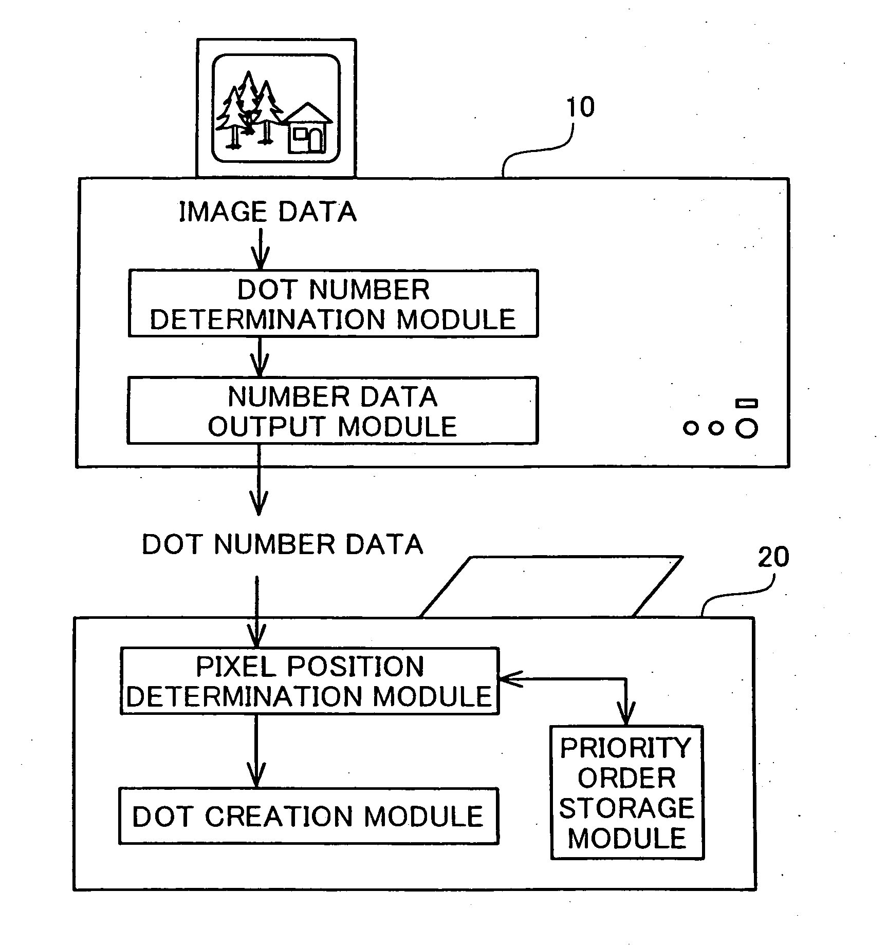
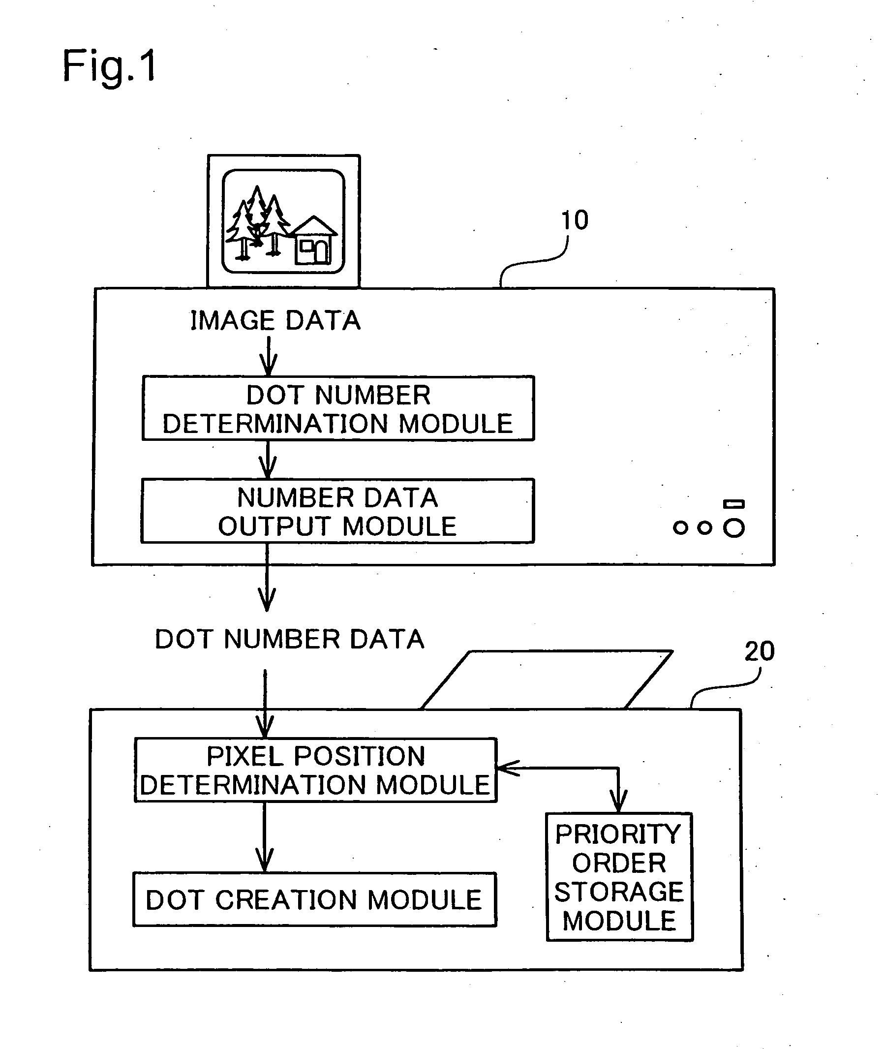
In an image output control system of the invention, an image processing device makes image data subjected to a preset series of image processing and supplies processed image data to an image output device to output a resulting processed image. The image processing device determines the number of dots to be created in each pixel group, which has a preset number of multiple pixels included in an image, and outputs the determined number of dots as dot number data to the image output device. The image output device stores multiple options for a priority order of individual pixels included in each pixel group for dot formation. In response to reception of the dot number data, the image output device selects one among the multiple options for the priority order, determines the positions of dot-on pixels in the pixel group, and actually creates dots at the determined positions of the dot-on pixels to output a resulting image. In the image output control system of the invention, the image processing device supplies the dot number data to the image output device. Even when an image includes a large number of pixels, this arrangement ensures quick data supply and thereby prompt image output.

Description

TECHNICAL FIELD [0001] The present invention relates to a technique of making image data subjected to a preset series of image processing and displaying a resulting processed image. More specifically the invention pertains to a technique of quickly transferring processed image data, which has gone through a preset series of image processing, to an image display device and thereby ensuring prompt display of a resulting processed image. BACKGROUND ART [0002] Image display devices that create dots on various display media, for example, printing media and liquid crystal screens, to display an image are widely used as the output device of diverse imaging equipment. The image display device divides an image into a number of small elements called pixels and creates dots in these pixels. Each pixel takes only either of two states, that is, a dot-on state and a dot-off state. The image as a whole may have areas of dense dot formation and areas of sparse dot formation. Each image is thus expr...

Claims


Application Information

Patent Timeline
Patent Type & Authority Applications(United States)
IPC IPC(8): H04N1/405G06T3/40
CPCH04N1/4057
Inventor KAKUTANI, TOSHIAKI
Owner SEIKO EPSON CORP
Learn More