
Outer mirror

Inactive Publication Date: 2006-06-22
MURAKAMI CORP
View PDF3 Cites 9 Cited by
  • Summary
  • Abstract
  • Description
  • Claims
  • Application Information

AI Technical Summary

Benefits of technology

[0014] According to this outer mirror, the mirror housing has the same structure as conventional mirror housings in that the mirror housing is supported by the protrusion on the upper face of the protrusion, i.e. rotatably fixed to the shaft standing upright on upper face of the protrusion. However, the outer mirror of the present invention has the auxiliary mirror positioned below the upper face of the protrusion. For this reason, the area diagonally forward the passenger seat of the vehicle body can be reflected on the outer mirror, unlike the conventional outer mirror. Because of this structure, the improvement in productivity is possible, while the outer mirror with excellent viewability is still achieved.
[0027] Since the driving device held in the mirror housing is located above the upper face of the protrusion, the structure of the conventional outer mirror in which the mirror housing is supported by the protrusion on the upper face of the protrusion can be adopted, which allows the use of the components including the driving device available on the market. As a result, the productivity is improved.

Problems solved by technology

However, the outer mirror of such a configuration has a problem in that it is impossible to adjust the tilt of the auxiliary mirror 124 in accordance with the visual point of a driver.
Therefore, it is difficult to apply the components of the outer mirror in FIG. 11, such as components related to rotation, to the outer mirror in FIG. 13, and there still remains a room for improvement from the viewpoint of manufacture.

Method used


Image

  • Outer mirror
  • Outer mirror
  • Outer mirror

Examples


first embodiment

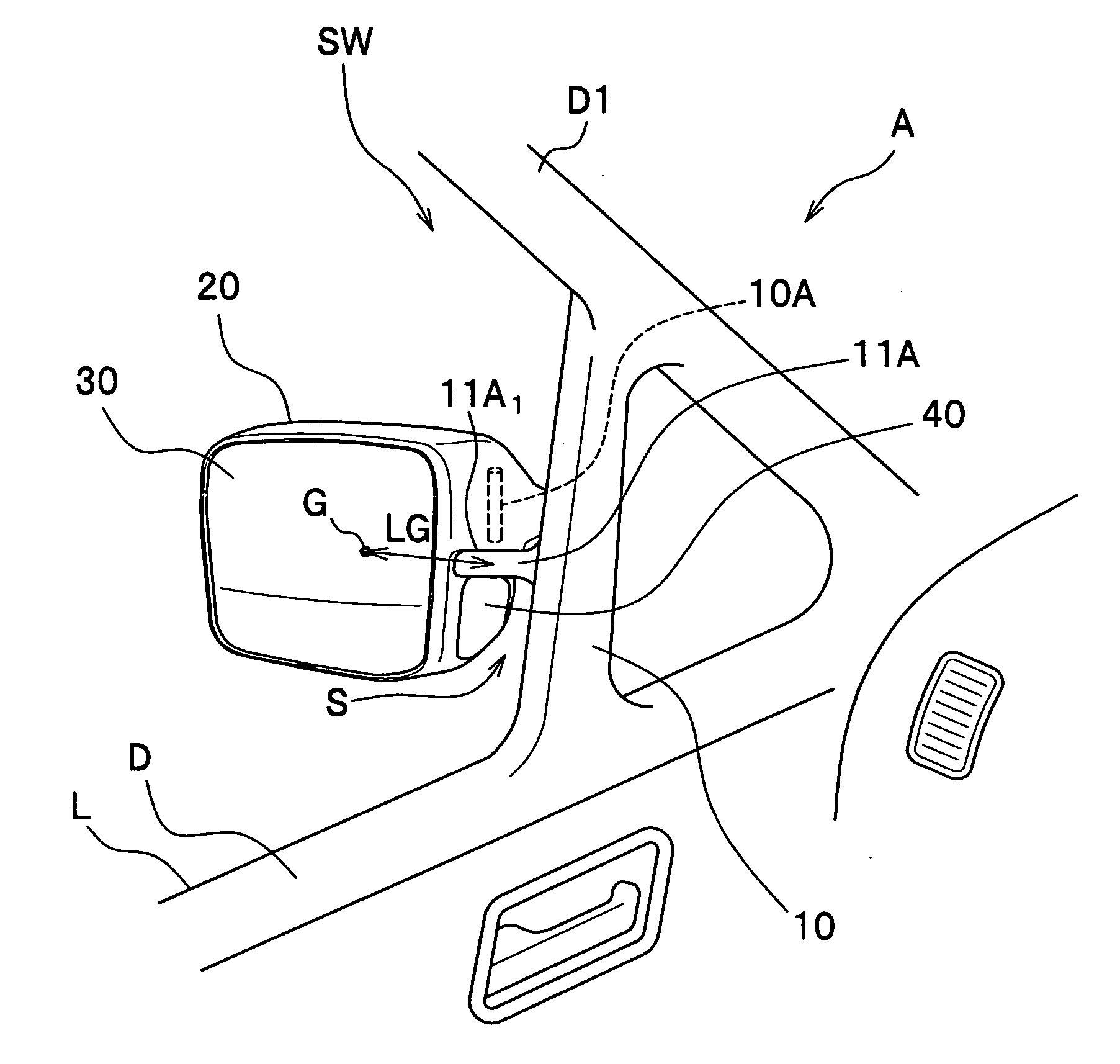
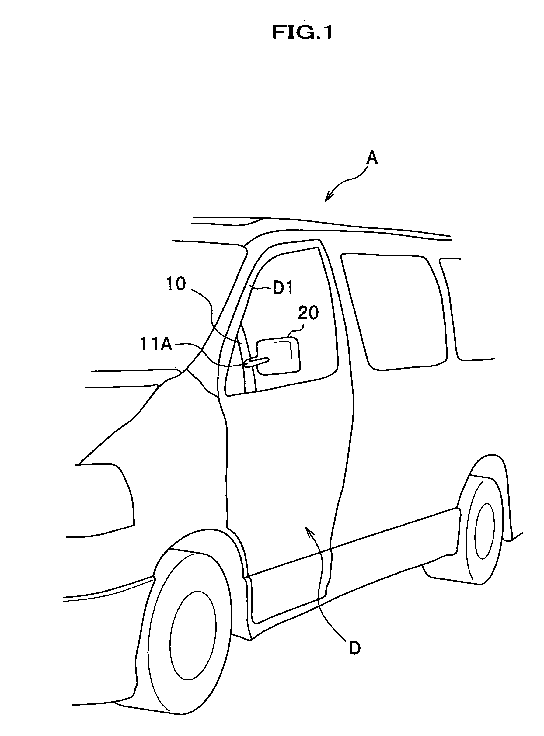
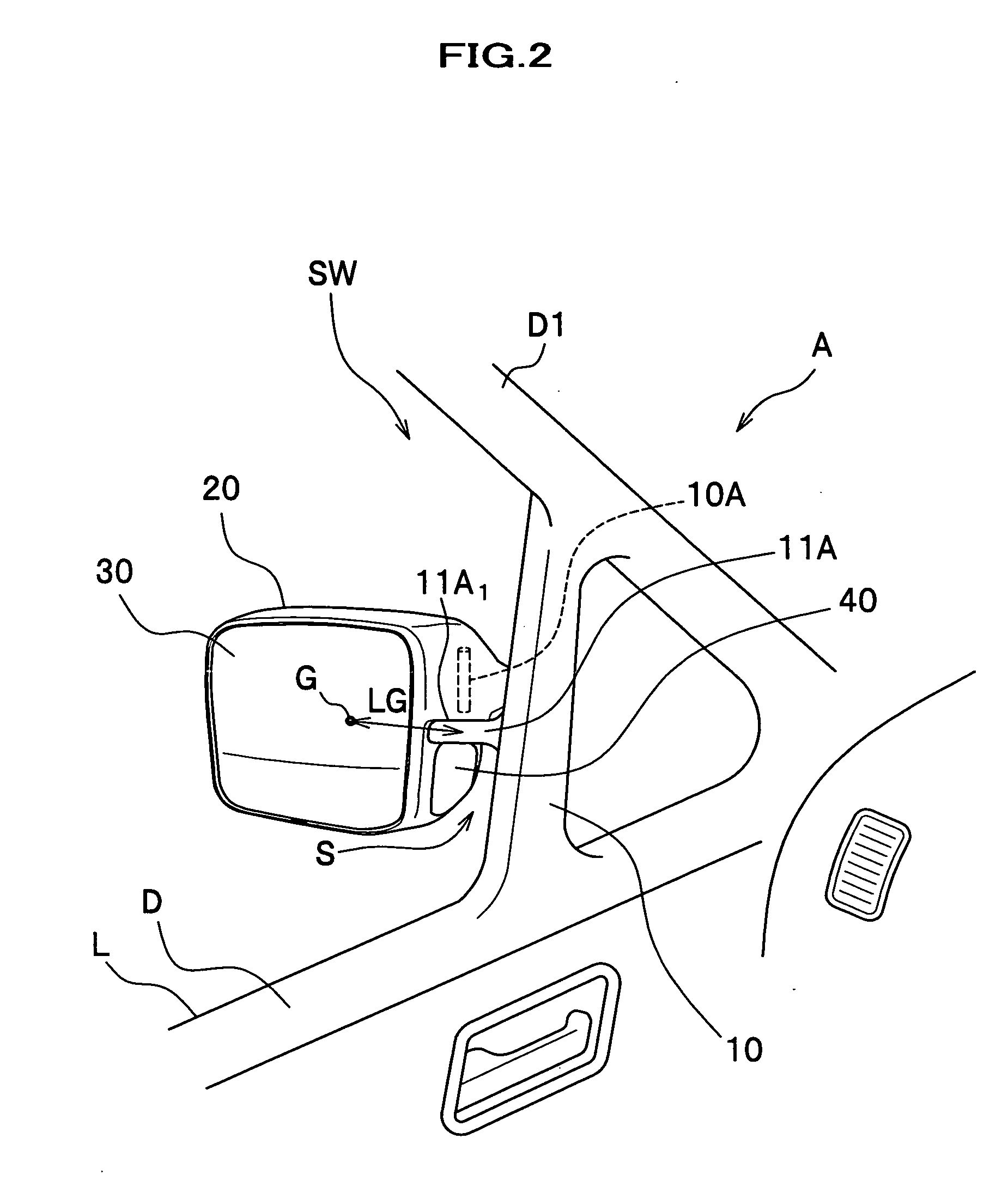
[0046] As shown in FIGS. 1 and 2, an outer mirror of this embodiment is what is called a door mirror, mounted on a front side door D on the passenger seat side of a vehicle body A. The outer mirror is composed of a mirror base 10 that has a protrusion 1A extending laterally from a side face of the vehicle body A, and a mirror housing 20 mounted on the upper side of the protrusion 11A. As shown in FIG. 2, a mirror 30 is provided on a rear face of the mirror housing 20, for viewing the rear area, and an auxiliary mirror 40 is provided on the vehicle body side surface of the mirror housing 20, for viewing an area diagonally forward the passenger seat of the vehicle body A, which is not seen directly from the driver seat.

[0047] In this embodiment, the outer mirror is an electrically-operated retractable mirror, and rotatably coupled to a shaft 10A mounted on the upper side of the protrusion 11A of the mirror base 10 (see FIG. 2).

[0048] Each component constituting the outer mirror will...

second embodiment

[0099] An outer mirror according to a second embodiment of the present invention is characterized in that an auxiliary rear view mirror 70 is introduced, as shown in FIGS. 9 and 10.

[0100] The auxiliary rear view mirror 70 is mounted on the mirror housing 60 at the position above the protrusion 11A (upper portion 60a on the side of the mirror housing 60). The mirror surface of the auxiliary rear view mirror 70 tilts down so as to slantingly face the ground. By introducing this auxiliary rear view mirror 70, the area around the rear side of the vehicle body A can be reflected.

[0101] According to this outer mirror, the area diagonally backward the side face of the vehicle body A can be checked by use of the auxiliary rear view mirror 70. When the auxiliary rear view mirror 70 being combined with the mirror 30 for viewing behind, the areas behind the vehicle body A, including those which in general cannot be seen from the driver seat, can be easily checked. In addition, since the auxi...


PUM


Abstract

An outer mirror includes a mirror base having a protrusion extending laterally from a side face of a vehicle body; a shaft fixed onto the protrusion; a mirror housing rotatably mounted on the shaft; a mirror for reflecting a rear view mounted on the mirror housing; and an auxiliary mirror mounted on the mirror housing. This auxiliary mirror is for reflecting an area diagonally forward the side face of the vehicle body and located below an upper face of the protrusion.

Description

CROSS-REFERENCE TO RELATED APPLIATIONS [0001] The present application claims priority under 35 U.S.C. § 119 to Japanese Patent Application No. 2004-366845, filed on Dec. 17, 2004, entitled “Outer Mirror”. The contents of that application are incorporated herein by reference in their entirety. BACKGROUND OF THE INVENTION [0002] 1. Field of the Invention [0003] The present invention relates to an outer mirror (exterior rearview mirror) to be attached to a side door of a vehicle or a surrounding area of the side door. [0004] 2. Description of the Related Art [0005] A typical outer mirror mainly includes, as shown in FIG. 11: a mirror base 110 that has a protrusion 100 extending laterally from a side face of a vehicle body (not shown); a shaft 111 fixed onto the upper surface of the protrusion 100; a driving unit 112 set on the shaft 111; a mirror housing 113 rotatably mounted on the shaft 111 through the driving unit 112; an actuator 114 for adjusting a tilt of a mirror surface; and a ...

Claims


Application Information

Patent Timeline
IPC IPC(8): G02B7/182
CPCB60R1/10B60R1/06B60R1/08
Inventor SUZUKI, HISAYAMATSUURA, MASAAKIMOTOMIYA, MASAHIRO
Owner MURAKAMI CORP
Learn More