Display and mobile device

Inactive Publication Date: 2006-06-22
SANYO ELECTRIC CO LTD
View PDF5 Cites 85 Cited by
  • Summary
  • Abstract
  • Description
  • Claims
  • Application Information

AI Technical Summary

Benefits of technology

[0020] In the display in accordance with the third aspect, the buffer member made of a cushioning material is provided at the portion of the upper metal frame facing the upper face of the first electronic component. Accordingly, even when

Problems solved by technology

In such a structure having a liquid crystal panel interposed between a metal bezel and a metal center chassis, however, the liquid crystal panel is brought into contact with the metal bezel and the metal center chassis

Method used


Image

  • Display and mobile device
  • Display and mobile device
  • Display and mobile device

Examples


Example

[0043] The following is a description of embodiments of the present invention, with reference to the accompanying drawings.

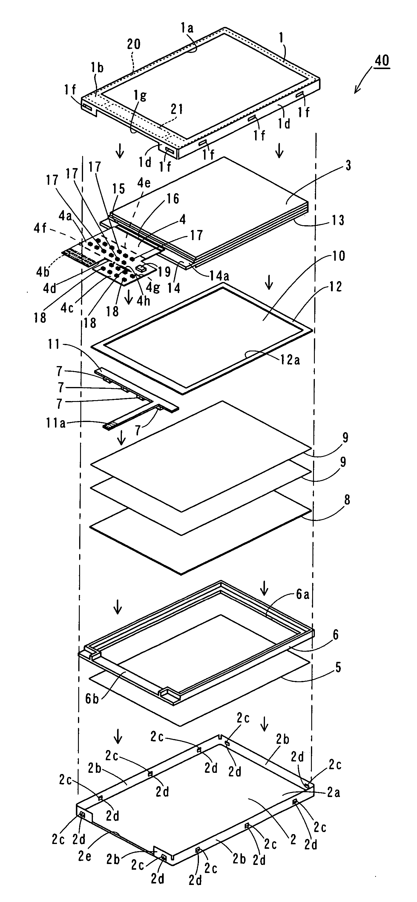
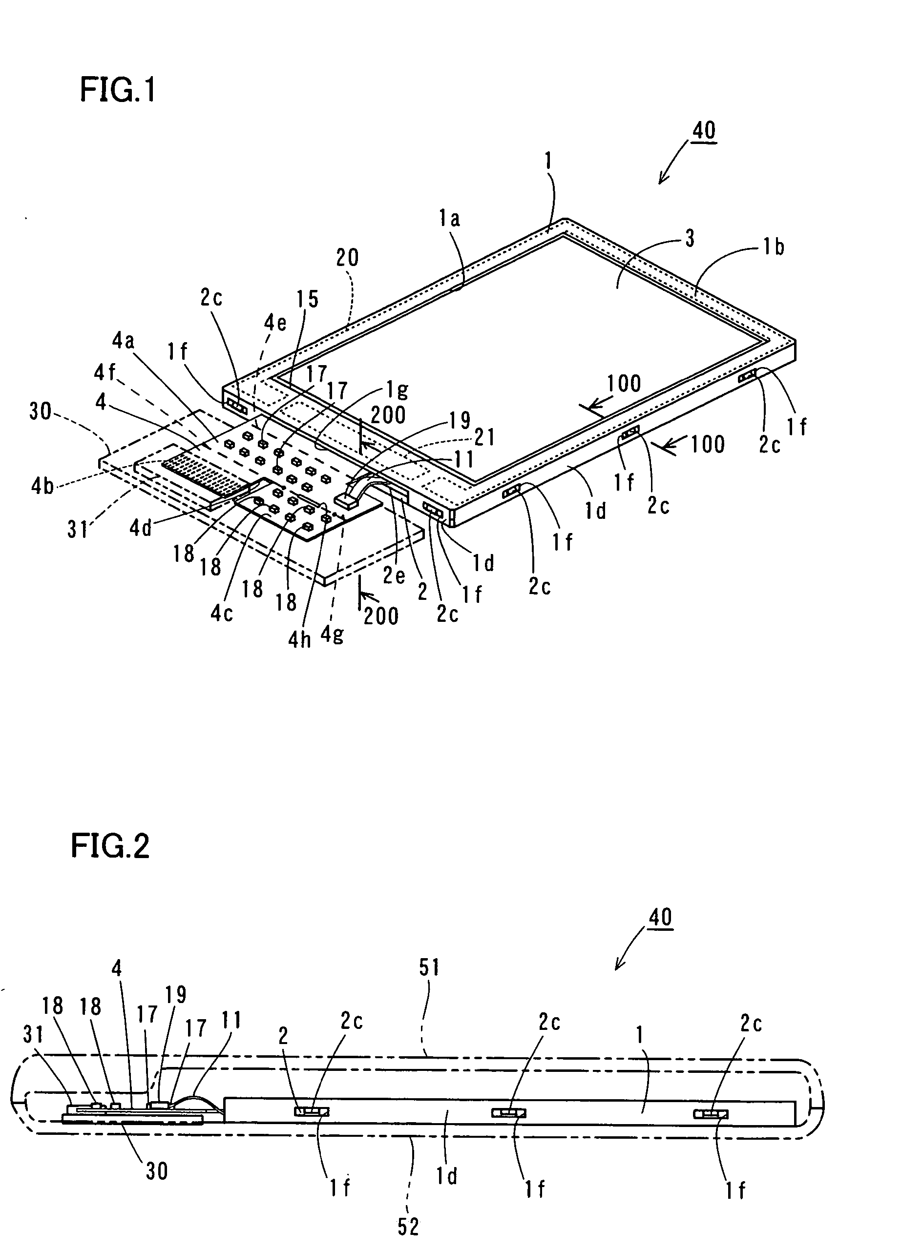
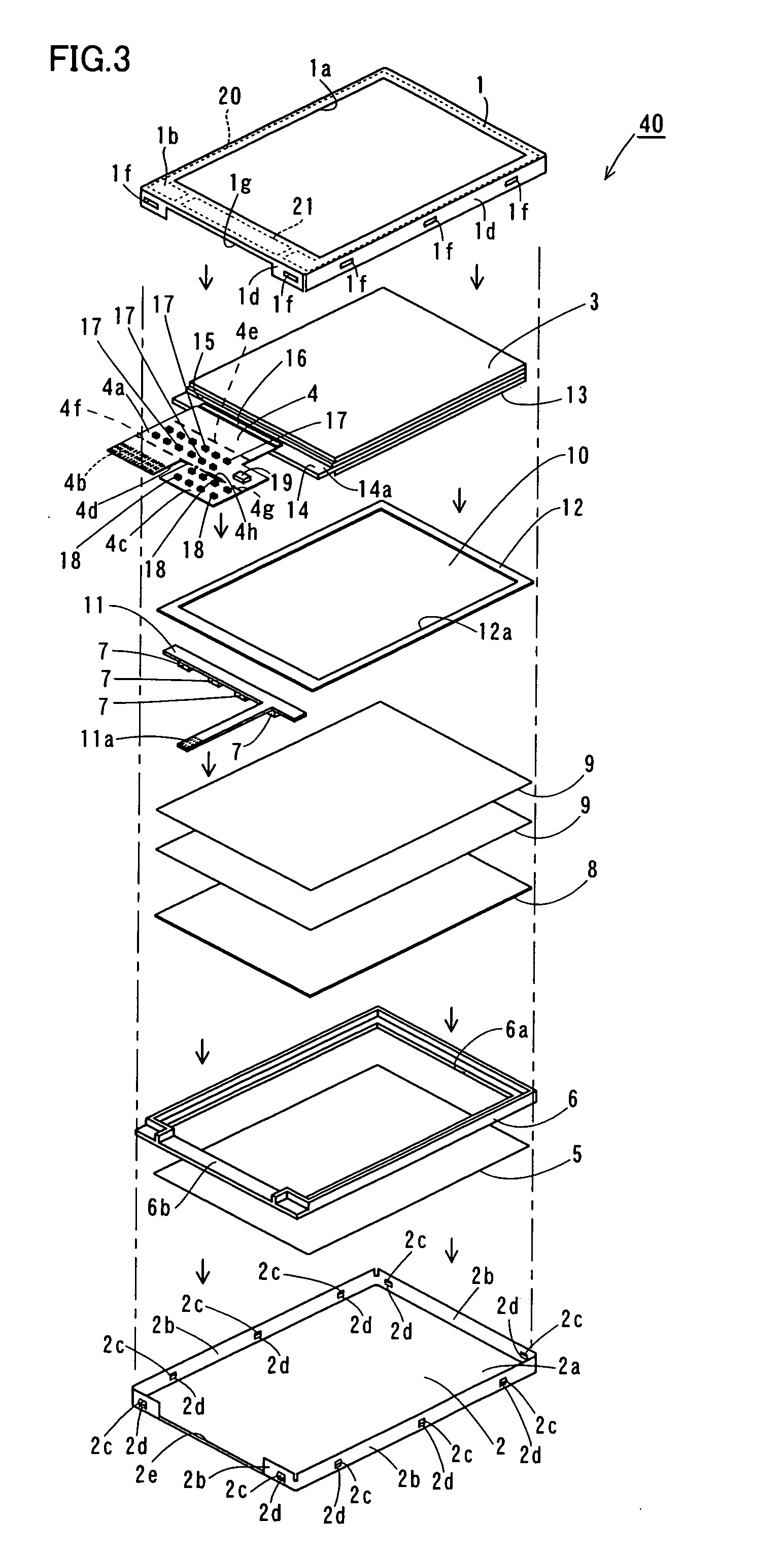
[0044] Referring to FIGS. 1 through 8, a LCD unit 40 in accordance with an embodiment of the present invention is described. In this embodiment, the LCD unit 40 is described as an example of the “display” in the claims.

[0045] As shown in FIGS. 1 and 2, the LCD unit 40 in accordance with this embodiment includes an upper frame 1 and a lower frame 2 that are plates made of metal, an upper deflecting plate 3 (see FIG. 1) that is disposed inside the upper frame 1 and the lower frame 2, and a panel flexible printed circuit board (panel FPC board) 4. The panel FPC board 4 is an example of the “flexible printed circuit board” in the claims. As shown in FIG. 2, the LCD unit 40 is housed in an upper chassis 51 and a lower chassis 52 of a mobile phone handset, and a connector inserting portion 4b (see FIG. 1) of the panel FPC board 4 of the LCD unit 40 is connected to a...


PUM


Abstract

A display and a mobile device are provided that can prevent damage to the display panel due to impact such as a fall. The display includes: a display panel; an upper metal frame that is disposed on the display panel, and houses the display panel; and a first buffer member that is made of a cushioning material, and is interposed between the upper metal frame and the upper face of the display panel.

Description

CROSS-REFERENCE TO RELATED APPLICATIONS [0001] The priority application No. JP2004-345592 upon which this patent application is based is hereby incorporated by reference. BACKGROUND OF THE INVENTION [0002] 1. Field of the Invention [0003] The present invention relates to a display and a mobile device, and more particularly, to a display that has a display panel, and a mobile device that includes the display. [0004] 2. Description of the Background Art [0005] An example of a conventional display having a display panel is disclosed in Japanese Unexamined Patent Publication No. 2004-29663. More specifically, Japanese Unexamined Patent Publication No. 2004-29663 discloses a liquid crystal display (LCD) unit that has the edge portion of a liquid crystal panel (a display panel) interposed between a metal bezel (an upper frame) and a metal center chassis. In such a structure having a liquid crystal panel interposed between a metal bezel and a metal center chassis, however, the liquid cryst...

Claims


Application Information

Patent Timeline
IPC IPC(8): G06F1/16G02F1/1333
CPCG02F1/133308G02F1/13452G02F2201/503G06F1/1601G06F1/1613G06F1/1637H04M1/0266H04M1/18H04M1/72519H04M1/724
Inventor OKUDA, TATSUMI
Owner SANYO ELECTRIC CO LTD
Why Eureka
Try Eureka