Mounting structure and mounting method for rotating disk storage device

a technology of rotating disk and mounting structure, which is applied in the direction of information storage, electrical apparatus construction details, record carrier construction details, etc., can solve the problems of affecting the performance of the drive in positioning the head to a required track during testing, affecting the proper testing of the drive, and affecting the proper testing

Inactive Publication Date: 2006-06-22
HITACHI GLOBAL STORAGE TECH NETHERLANDS BV
View PDF8 Cites 33 Cited by
  • Summary
  • Abstract
  • Description
  • Claims
  • Application Information

AI Technical Summary

Benefits of technology

[0014] According to the present invention, a mounting structure is adapted to attach and remove the rotary disk storage device thereto and therefrom within a short period of time. According to the present invention, a mounting structure that allows the magnetic disk drive to be positively secured in position can be provided. Furthe

Problems solved by technology

As a result, vibrations occur in a housing forming an outside of the magnetic disk drive.
If the housing of the magnetic disk drive vibrates, the drive's performance of positioning a head to a required track during

Method used


Image

  • Mounting structure and mounting method for rotating disk storage device
  • Mounting structure and mounting method for rotating disk storage device
  • Mounting structure and mounting method for rotating disk storage device

Examples


Embodiment Construction

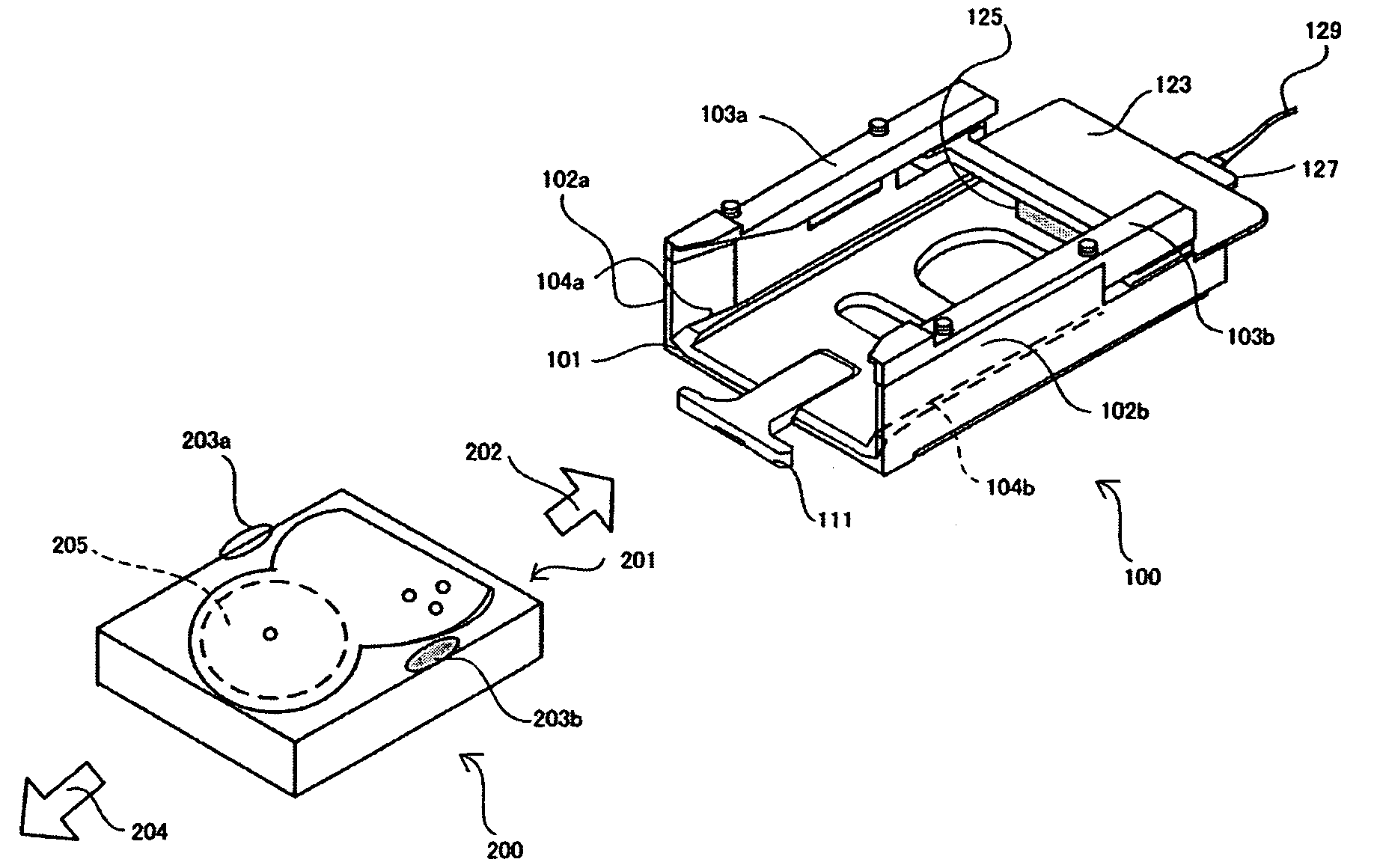
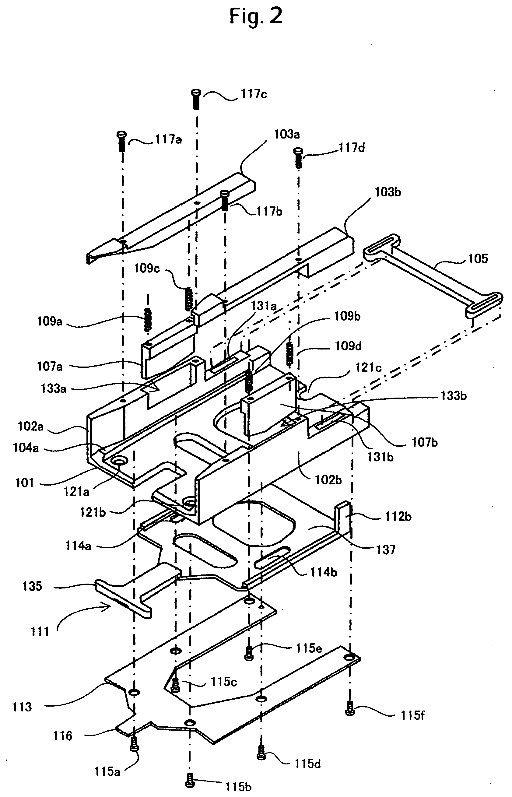
[0023]FIG. 1 is a perspective view showing a mounting structure 100 and a magnetic disk drive 200 according to a specific embodiment of the present invention. A frame 101 includes a pair of sidewalls 102a, 102b, a pair of rails 104a, 104b, and a lever 111. A pair of upper frames 103a, 103b is attached to the upper portion of the frame 101. The frame 101 is further mounted with a circuit board 123. The circuit board 123 includes a device connector 125 and a plug 127 connected to the device connector 125. The plug 127 is connected to a test computer with a wire 129.

[0024] The magnetic disk drive 200 houses a magnetic disk 205 therein and is covered with a housing on an outside thereof. An interface connector (not shown) connectable to the device connector 125 is attached on the side of a surface of the housing represented by reference numeral 201. How to mount the magnetic disk drive 200 to the mounting structure 100 and connect the interface connector to the device connector 125 wil...


PUM


Abstract

Embodiments of the invention provide a mounting structure adapted to easily attach and remove a magnetic disk drive thereto and therefrom. In one embodiment, the mounting structure includes a device connector connectable to an interface connector. A clamper moves between a fixing position and a releasing position to secure or release an end portion of a housing. A lever keeps the clamper at the releasing position until the interface connector is connected to the device connector when a magnetic disk drive is pushed into a mounting structure. The clamper positions the clamper at the fixing position after the interface connector has been connected to the device connector.

Description

CROSS-REFERENCES TO RELATED APPLICATIONS [0001] This application claims priority from Japanese Patent Application No. JP2004-367638, filed Dec. 20, 2004, the entire disclosure of which is incorporated herein by reference. BACKGROUND OF THE INVENTION [0002] The present invention relates to a mounting structure used for connecting a rotating disk storage device, such as a magnetic disk drive or an optical magnetic disk drive, to an external connector. [0003] A magnetic disk drive as an example of a rotating disk storage device is subjected to operating tests, parameter setting, and adjustments by being connected to an external test machine after assembly of parts. If subjected to mass production, a large number of magnetic disk drives are mounted in a test chamber all at once. An interface connector is then connected to a device connector of the chamber and the test is carried out by connecting the device connector to a test computer. The test chamber includes a mounting structure for...

Claims


Application Information

Patent Timeline
IPC IPC(8): G06F1/16
CPCG06F1/184G06F1/187G11B33/022G11B33/122G11B33/124
Inventor TAKAHASHI, SATOSHITSUYAMA, MASASHI
Owner HITACHI GLOBAL STORAGE TECH NETHERLANDS BV
Why Eureka
Try Eureka