Image coding control method and device

Inactive Publication Date: 2006-06-22
KK TOSHIBA
View PDF12 Cites 46 Cited by
  • Summary
  • Abstract
  • Description
  • Claims
  • Application Information

AI Technical Summary

Benefits of technology

[0014] According to the embodiments of the invention, by forming the set of the secondary number of coded bits—coding distortion pairs for sequentially forming the convex hull, the prediction mode and the quantization parameter to be used for the coding can be determined from the optimal number of coded bits—coding distortion pairs while considering the overall computational complexity. Accordingly, the proper prediction mode and the quantization parameter are determined with a small computa

Problems solved by technology

It is said that it greatly affects the coding performance how the switching operation is carried out.
However, this method pays no attention to the actual number of coded bits (rate) and the distortion, and thus it can be hardly said that the switching operation of the prediction mode which is optimal in the relationship between the number of coded bits and the distortion is carried out.
Accordingly, this method does not greatly enhance the coding efficiency.
Therefore, when the quantization parameter is varied or when the shape of the number of coded bits—coding distortion function is different from t

Method used


Image

  • Image coding control method and device
  • Image coding control method and device
  • Image coding control method and device

Examples


Embodiment Construction

[0026] Embodiments according to the invention will be described hereunder with reference to the accompanying drawings.

(1) Construction of Image Coding Device

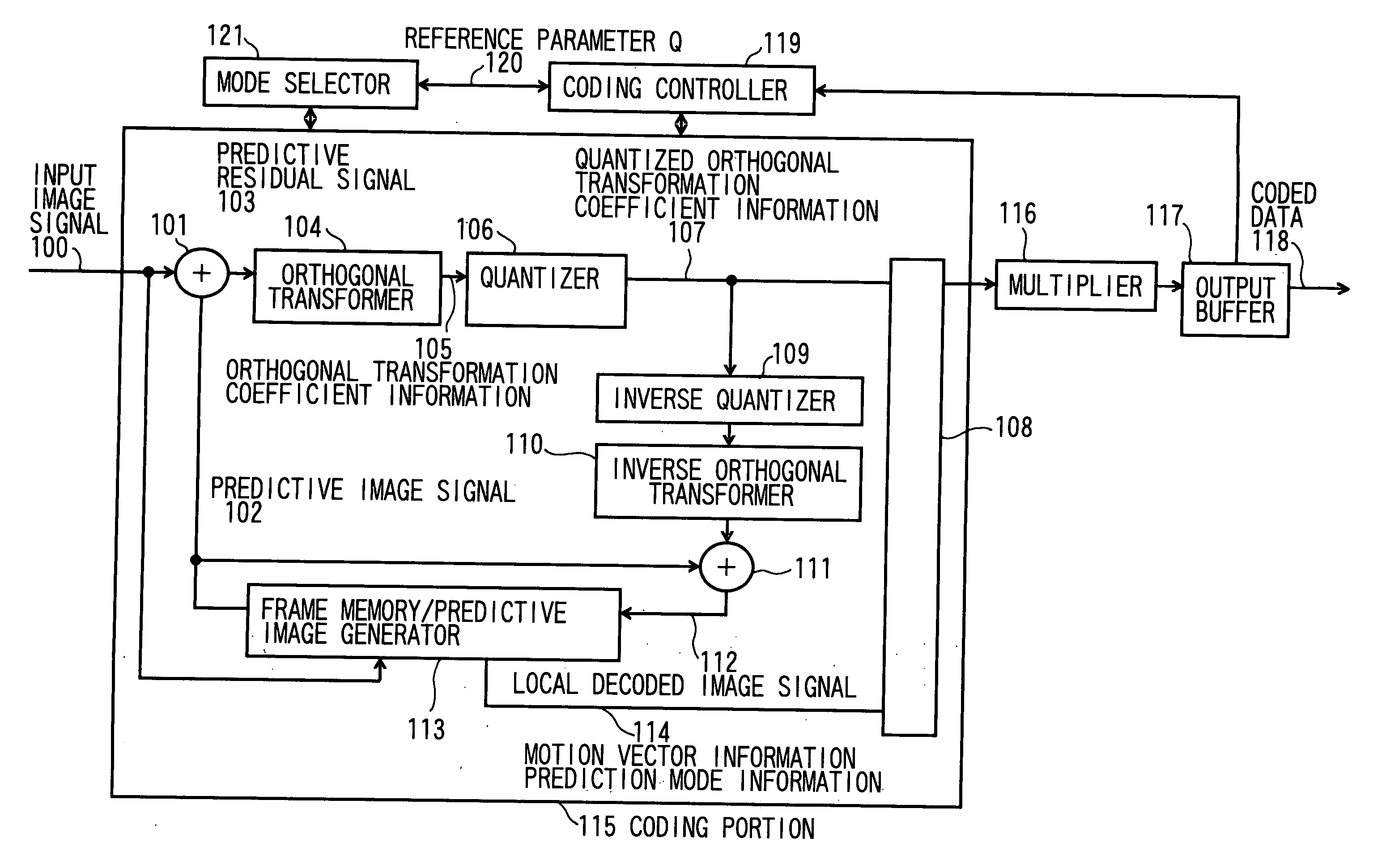
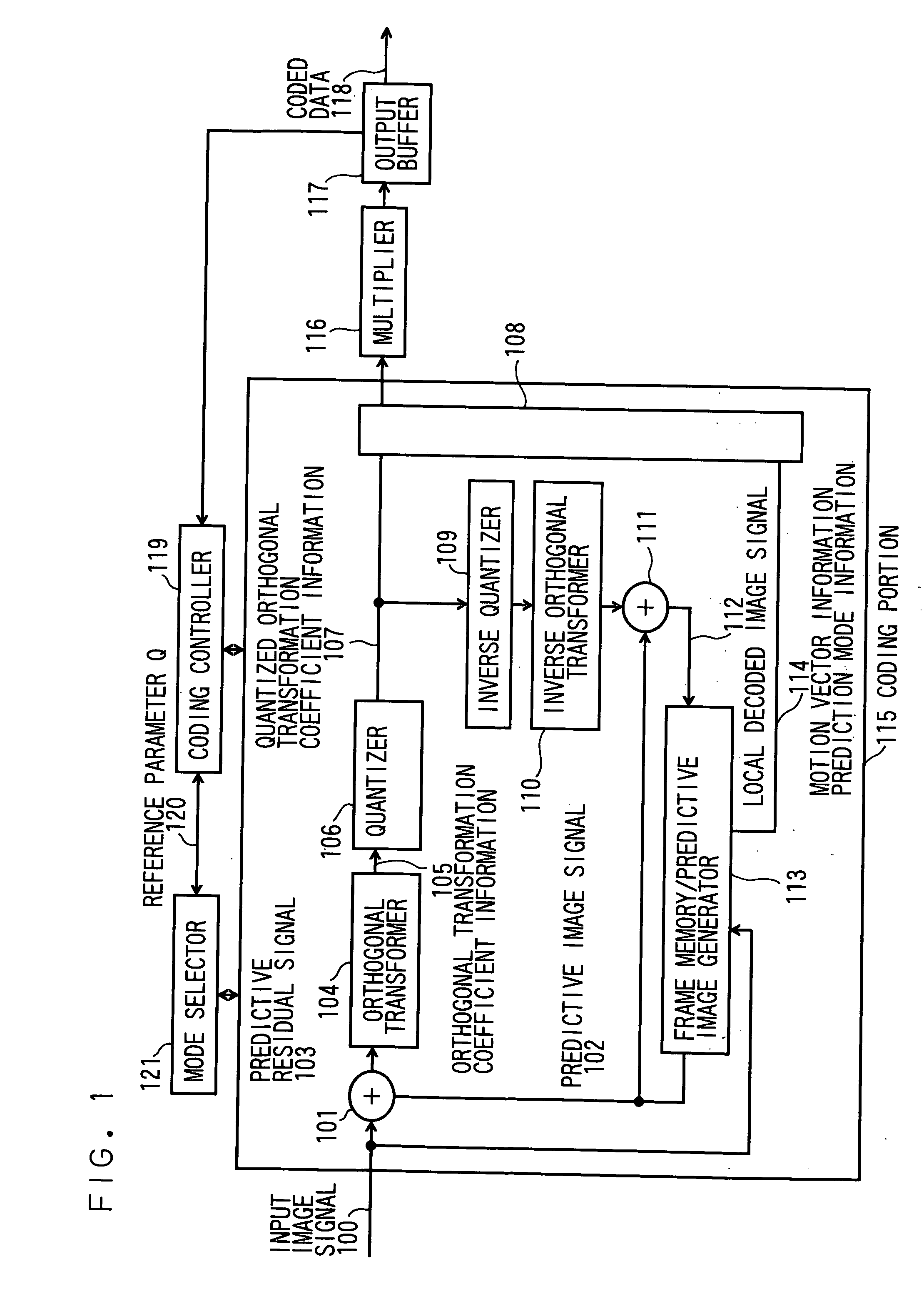
[0027]FIG. 1 shows an image coding device for coding a motion picture according to an embodiment of the invention.

[0028] A motion picture signal is input as an image signal 100 to the image coding device on a frame basis.

[0029] The difference between an input image signal 100 and a predictive image signal 102 is taken by a subtracter 101 to generate a prediction error signal 103. On the prediction error signal 103 thus generated, orthogonal transformation, for example, discrete cosine transformation (DCT) is conducted by an orthogonal transformer 104. Orthogonal transformation coefficient information 105, for example, DCT coefficient information is achieved in the orthogonal transformer 104. The orthogonal transformation efficiency information 105 is quantized by a quantizer 106 to achieve quantized orthogonal transformatio...


PUM


Abstract

Image coding having high coding efficiency is provided with a small computational complexity by properly determining a prediction mode and a quantization parameter. When an image is coded by a prediction mode selected from plural prediction modes every any coding unit, an undetermined multiplier λ is first calculated from a quantization parameter (function S301) Subsequently, the cost of each of R-D points (pairs of number of coded bits and coding distortion that correspond to plural combinations of prediction modes and quantization parameters) is calculated (function S305) on the basis of the undetermined multiplier λ while generation and estimation of the R-D points and deletion of the points (functions S302-S304) are repeated every coding unit, for example, every macroblock, and the optimal combination of the prediction mode and the quantization parameter is determined on the basis of the R-D point providing the minimum cost.

Description

CROSS-REFERENCE TO RELATED APPLICATIONS [0001] This application is based upon and claims the benefit of priority from the prior Japanese Patent Application No. 2004-372357, filed on Dec. 23, 2004; the entire contents of which are incorporated herein by reference. TECHNICAL FIELD [0002] The present invention relates image coding control method and device for motion pictures or still images. BACKGROUND OF THE INVENTION [0003] According to a motion picture coding standard system such as ITU-T H.261, H.263, H.264, ISO / IEC MPEG-2, MPEG-4 part 2 or the like, coding is carried out every coding unit called as a macroblock while switching a prediction mode. It is said that it greatly affects the coding performance how the switching operation is carried out. [0004] One of the methods of switching the prediction mode is disclosed in TMN9 which is a test model of ITU-T H. 263 (see Non-patent Document 1, ITU-T, Study Group 16: “Video Codec Test Model, Near-term, Version 9 (TMN9)”, Document: Q15-...

Claims


Application Information

Patent Timeline
IPC IPC(8): H04N11/04H04B1/66H04N7/12H04N11/02H04N19/50G06T9/00H04N1/413H04N19/103H04N19/124H04N19/127H04N19/136H04N19/146H04N19/147H04N19/154H04N19/172H04N19/174H04N19/176H04N19/177H04N19/19H04N19/196H04N19/40H04N19/503H04N19/593H04N19/60H04N19/61H04N19/91
CPCH04N19/176H04N19/147H04N19/61H04N19/19H04N19/124H04N19/186H04N19/107
Inventor CHUJOH, TAKESHI
Owner KK TOSHIBA
Why Eureka
Try Eureka