Method and apparatus for correcting motion in image reconstruction

a motion correction and image reconstruction technology, applied in the field of non-invasive imaging, can solve problems such as inconsistencies in imaging data acquired, motion-related image artifacts, and present certain challenges for non-invasive imaging techniques

Active Publication Date: 2006-06-22
GENERAL ELECTRIC CO
View PDF37 Cites 155 Cited by
  • Summary
  • Abstract
  • Description
  • Claims
  • Application Information

AI Technical Summary

Problems solved by technology

Dynamic internal tissues, such as the heart, may present certain challenges for non-invasive imaging techniques, however.
For example, in cardiac imaging, the motion of the heart results in inconsistencies in imaging data acquired at different phases of the cardiac cycle.
These inconsistencies cause various motion-related image artifacts, such as blurring, streaking, or discontinuities, in the images and / or volumes generated with the imaging data.
However, these various techniques, alone and in combination, are not currently capable of providing a temporal resolution of approximately 20 ms or less, which is desirable to “freeze” cardiac motion, thereby minimizing motion related artifacts in the reconstructed images.

Method used


Image

  • Method and apparatus for correcting motion in image reconstruction
  • Method and apparatus for correcting motion in image reconstruction
  • Method and apparatus for correcting motion in image reconstruction

Examples


Embodiment Construction

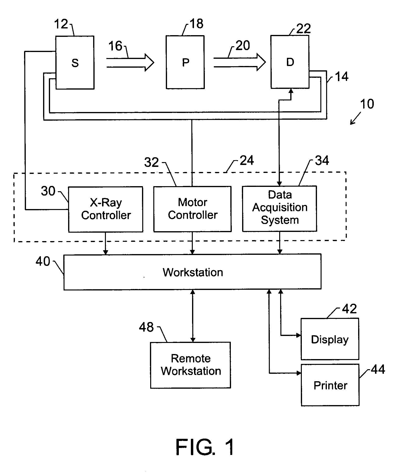
[0010]FIG. 1 illustrates diagrammatically an imaging system 10 for acquiring and processing image data. In the illustrated embodiment, system 10 is an imaging system employing a C-arm type gantry designed to acquire X-ray projection data at various viewing angles about an imaging volume, to reconstruct the projection data into an image, and to process the image data for display and analysis in accordance with the present technique. For example, the imaging system 10 may be a fixed C-arm vascular imaging system, such as may be present in a dedicated imaging or examination room, or a mobile C-arm vascular imaging system, such as may be used in surgical procedures or moved within a medical facility as needed. The imaging system 10 may also be a tomosynthesis system or other imaging system configured to acquire image data over a limited angular range or a computed tomography (CT system configured to acquire image data over a complete angular range.

[0011] In the embodiment illustrated i...


PUM

PropertyMeasurementUnit
angleaaaaaaaaaa
correlation thresholdaaaaaaaaaa
speedaaaaaaaaaa

Abstract

A plurality of projection images are acquired over an angular range during the slow rotation of a C-arm gantry having a source and detector. Phase-specific reconstructions are generated from the plurality of projections, wherein each phase-specific reconstruction is generated generally from projections acquired at or near the respective phase. In one embodiment, a plurality of motion estimates are generated based upon the phase-specific reconstructions. One or more motion-corrected reconstructions may be generated using the respective motion estimates and projections. The motion-corrected reconstructions may be associated to form motion-corrected volume renderings.

Description

BACKGROUND OF THE INVENTION [0001] The present invention relates generally to the field of non-invasive imaging and more specifically to the field of medical imaging for dynamic, internal tissue, such as cardiac tissue. In particular, the present invention relates to the characterization of internal motion and to the reconstruction of images that account for the characterized motion. [0002] Non-invasive medical imaging broadly encompasses techniques for generating images of the internal structures or regions of a person that are otherwise inaccessible for visual inspection. One of the best known uses of non-invasive imaging is in the medical arts where these techniques are used to generate images of organs and / or bones inside a patient which would otherwise not be visible. One class of medical non-invasive imaging techniques is based on the differential transmission of X-rays through a patient. For example, a simple X-ray imaging technique may involve generating X-rays using an X-ra...

Claims


Application Information

Patent Timeline
Patent Type & Authority Applications(United States)
IPC IPC(8): A61B6/00G01N23/00G21K1/12H05G1/60
CPCG01N23/046G06T7/20G06T11/005G01N2223/612G06T2211/436A61B6/5258G01N2223/419G06T2211/412
Inventor LANGAN, DAVIDEDIC, PETERALYASSIN, ABDALMAJEIDCLAUS, BERNHARDMANAK, JOSEPHMILLER, JAMES V.
Owner GENERAL ELECTRIC CO
Why Eureka
Try Eureka