
Stress measurement method and its apparatus

a technology of stress measurement and apparatus, applied in the direction of apparatus for force/torque/work measurement, force measurement, instruments, etc., can solve the problems of difficult industrial use application and always complicated measurement results

Inactive Publication Date: 2006-06-22
TAKAHASHI SENNOSUKE
View PDF2 Cites 23 Cited by
  • Summary
  • Abstract
  • Description
  • Claims
  • Application Information

AI Technical Summary

Benefits of technology

[0042] This invention is composed and operated described above. The time of flight or the wave velocity of the object is measured by use of longitudinal or transverse ultrasonic wave and the inherent stress dependent coefficient is determined. As the result, it is possible to obtain the stress induced in the object rapidly and quantitatively at real time by use of this stress measurement method and the apparatus.

Problems solved by technology

Therefore these measurements are always complicated in the preparation of both sensors of longitudinal and transverse waves.
Moreover in this patent reference 1, the relation between the sound velocity ratio R and the stress σ was not disclosed, so it was difficult to apply for industrial use.

Method used


Image

  • Stress measurement method and its apparatus
  • Stress measurement method and its apparatus
  • Stress measurement method and its apparatus

Examples


Embodiment Construction

[0051] Followings is the explanation to perform this invention in the best practical application using the appended figures.

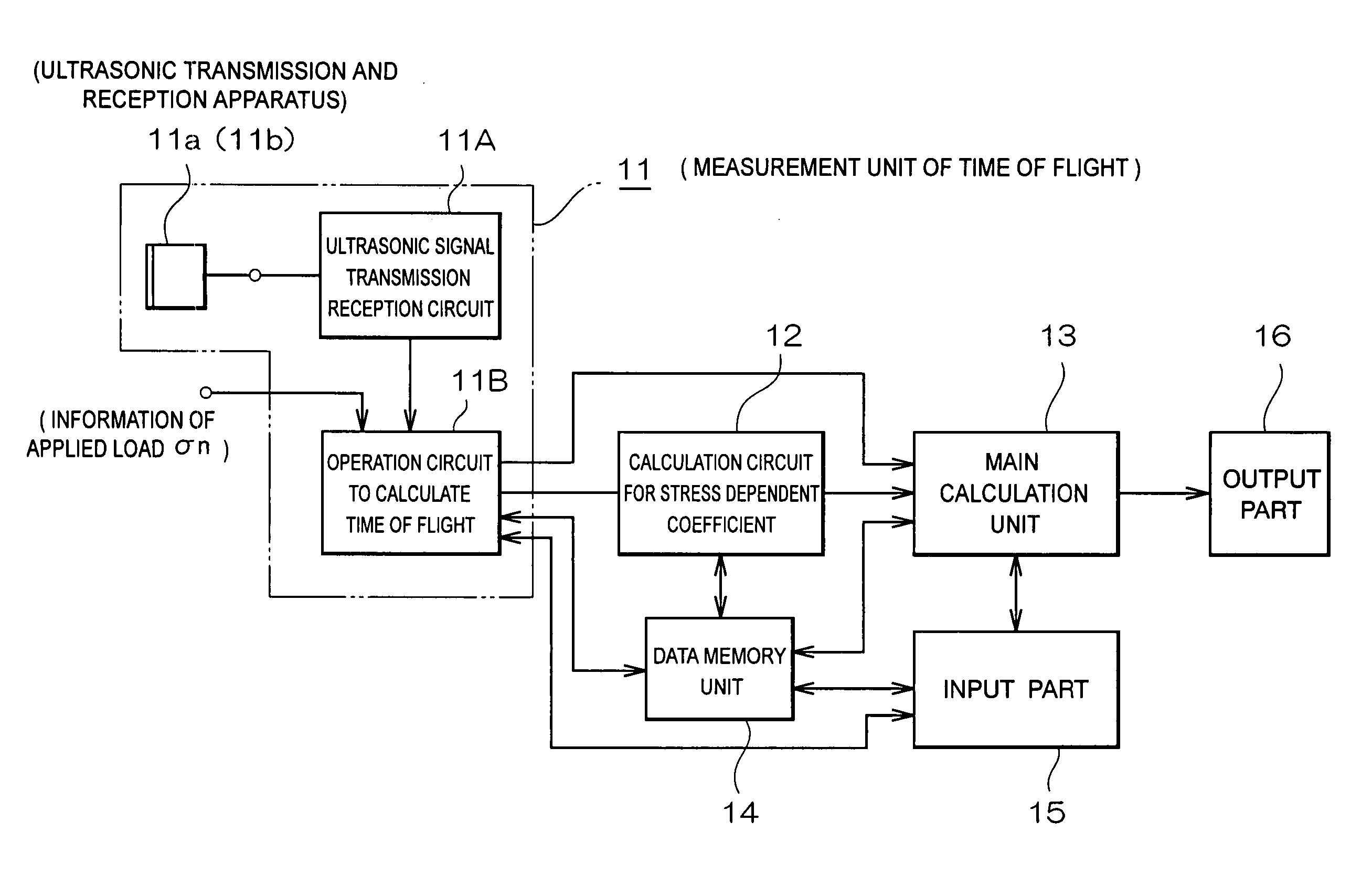
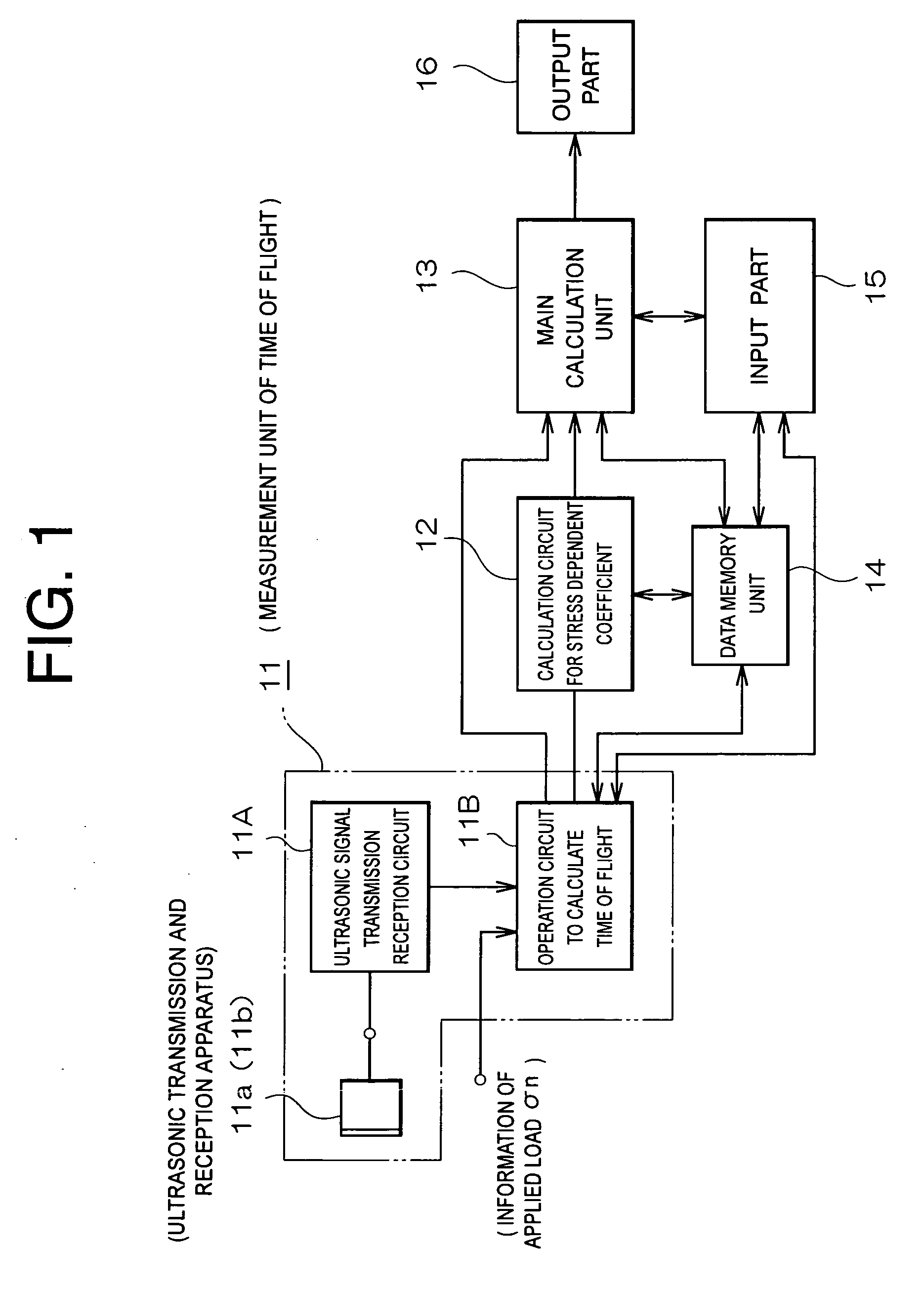
[0052] As shown in FIG. 1, this practical application form is composed of (operation 11) the measurement unit of time of flight corresponding the change with the load applied on the object 1 or the other part 1A consisted as same material as the object 1, (operation 12) the calculation unit of the stress dependent coefficient α using above time of flight (the calculation circuit for stress dependent coefficient), and (operation 13) the main calculation unit of the stress σ of the object using the data obtained from the operation 11 and 12.

[0053] The load applying apparatus 21 is also equipped in the operation 11 to measure the time of flight. In FIG. 1 mark 14 shows a memory part of information and mark 15 shows a part to input the necessary data or operation command. Mark 16 shows a part to output the data of the stress of the object 1 and print them.

[0054]...


PUM

PropertyMeasurementUnit
lengthaaaaaaaaaa
lengthaaaaaaaaaa
stressaaaaaaaaaa

Abstract

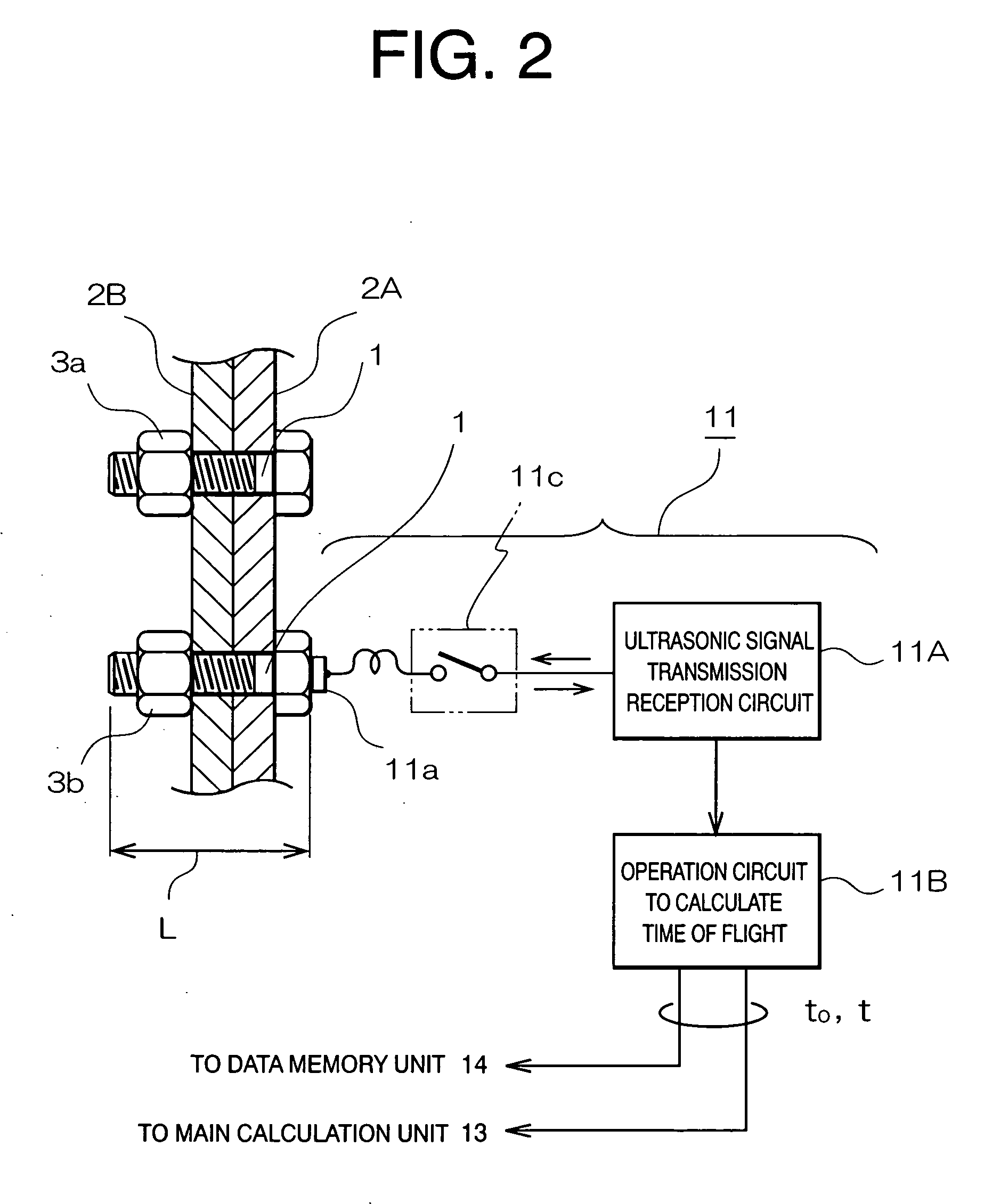
Time of flight of sound t0, tn propagating through fixed one face to another of the object under zero load (σ0) and changed applied load (σn) respectively are measured, then stress dependent coefficient α peculiar to material of the object can be obtained from above data and the equation determined beforehand α=f(Δtn, σn) using stress dependent coefficient calculation circuit 12. Time of flight of sound t propagating through one face to another of the object 1 at the determined place under applied unknown load is measured next. Time of flight tn, t0 are measured by time of flight measurement system 11. This invention consists of the stress measurement method and the apparatus to calculate real stress caused in the practically equipped object using equationσ=f(Δt, α) determined beforehand based on time of flight t and stress dependent coefficient α mentioned above.

Description

BACKGROUND OF THE INVENTION [0001] 1. Field of the Invention [0002] This invention relates to a stress measurement method and its apparatus. The stress of material in the process, goods (for example, single crystal of semiconductor etc.) and unknown stresses in the composed parts under the power station, high pressure plants, airplane, vehicles, various kinds of device, and the material of parts inthe other constructions etc. are especially able to rapidly quantitatively obtain by use of this invention. [0003] 2. Related Art [0004] The various kind of vehicles or constructions mainly made of metals are generally used for semi permanent term. Contrarily, each part is necessary to be repaired or exchanged with a lapse of determined time because of its partial damage. [0005] In the various kinds of vehicle, not only axle supporting weight of vehicle but also connective bolt and power transmission are under continuously or repeatedly dynamical or static load. The material having the str...

Claims


Application Information

Patent Timeline
Patent Type & Authority Applications(United States)
IPC IPC(8): G01L1/00
CPCG01L1/162
Inventor TAKAHASHI, SENNOSUKE
Owner TAKAHASHI SENNOSUKE
Learn More