Developing method and developing device using the same

a technology of developing method and developing device, which is applied in the field of developing method, can solve the problems of uneven coating, uneven coating, scattering of developer, etc., and achieve the effects of low fluctuation in image density and triboelectrification, and high solid uniformity

Active Publication Date: 2005-10-27
CANON KK
View PDF9 Cites 17 Cited by
  • Summary
  • Abstract
  • Description
  • Claims
  • Application Information

AI Technical Summary

Benefits of technology

[0009] An object of the present invention is to provide a developing method using a multi-stage developing system with which insufficient coating such as stripe or unevenness does not occur in a developer layer on a developing sleeve, accumulation of an external additive and toner spent on and to the surface of a carrier are prevented, and hence solid uniformity is high and fluctuations in image density and triboelectrification are small for a long period of time under various environments.

Problems solved by technology

However, it is difficult to form a uniform developer layer on each of the multiple developing sleeves.
In particular, if transportation of a developer between developing sleeves fails, scattering of the developer, uneven coating, or the like is apt to occur.
In addition, stress to be applied to the developer between a developing sleeve and a developer layer thickness regulating member (between S and B) or between a developing sleeve and another developing sleeve (between S and S) is large, so deterioration of the developer is apt to occur.
However, in the multi-stage developing system, when such a two-component developer having flowability is used, it becomes difficult to form a uniform developer layer on each of the multiple developing sleeves, and, in particular, transportation of the developer between developing sleeves is apt to be nonuniform, so insufficient coating or the like may occur.
However, an improvement of a developer having flowability suitable for a multi-stage developing system still requires further investigation.

Method used


Image

  • Developing method and developing device using the same
  • Developing method and developing device using the same
  • Developing method and developing device using the same

Examples


example 1

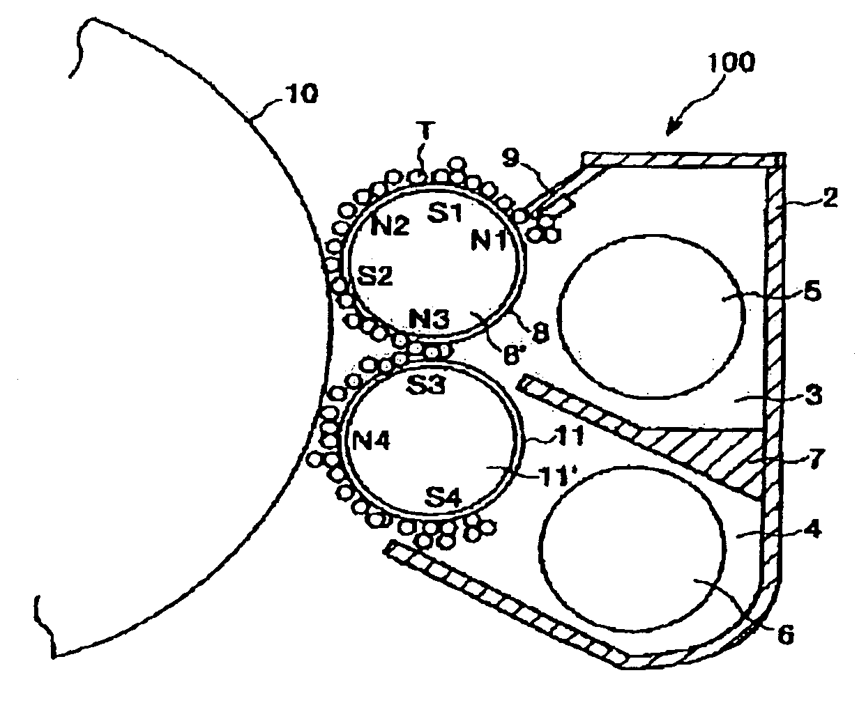
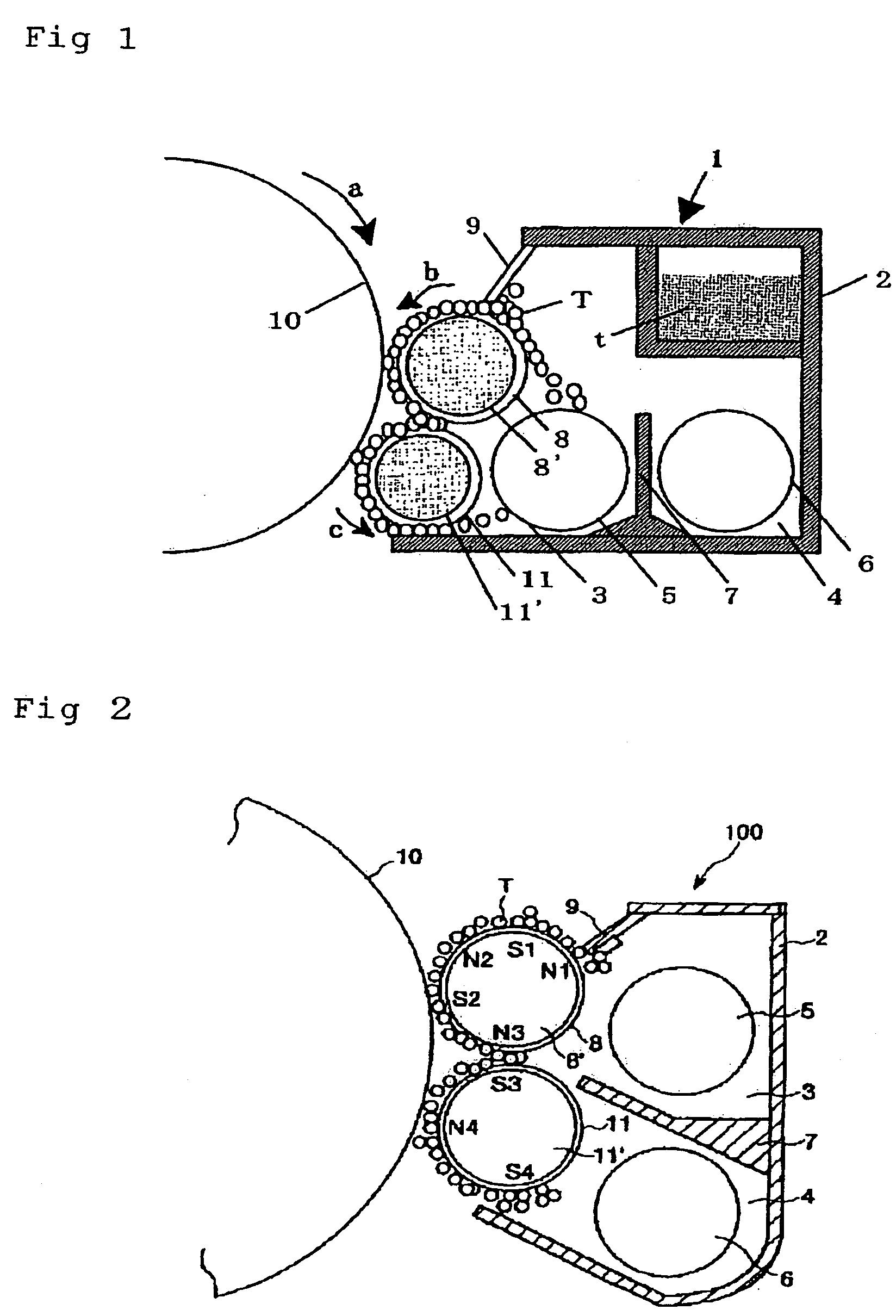
[0359] A full-color copying machine CLC5000 manufactured by Canon Inc. was reconstructed as follows. First, a laser spot diameter was narrowed down so as to be able to output at 600 dpi. Second, as shown in FIG. 1, the number of developing sleeves in a developing unit was changed to two: a developing sleeve on an upstream side (having a diameter of 20 mm) and a developing sleeve on a downstream side (having a diameter of 16 mm) each of which was opposed to the photosensitive drum. Third, the surface layer of a fixing roller in a fixing unit was changed to a PFA tube and an oil applying mechanism was removed. By using the two-component developer (D-1) and the reconstructed machine, image output and evaluation were performed under a normal-temperature-and-normal-humidity environment (N / N; 23° C., 50% RH), a normal-temperature-and-low-humidity environment (N / L; 23° C., 5% RH); and a high-temperature-and-high-humidity environment (H / H; 30° C., 80% RH) while the toner (B-1) was replenish...

examples 2 to 10

[0386] Image output and evaluation were performed in the same manner as in Example 1 except that: the two-component developer (D-1) was changed to any one of the two-component developers (D-2) to (D-10); and toner corresponding to each two-component developer shown in Table 3 was replenished. Table 4 shows the results of the evaluation.

example 11

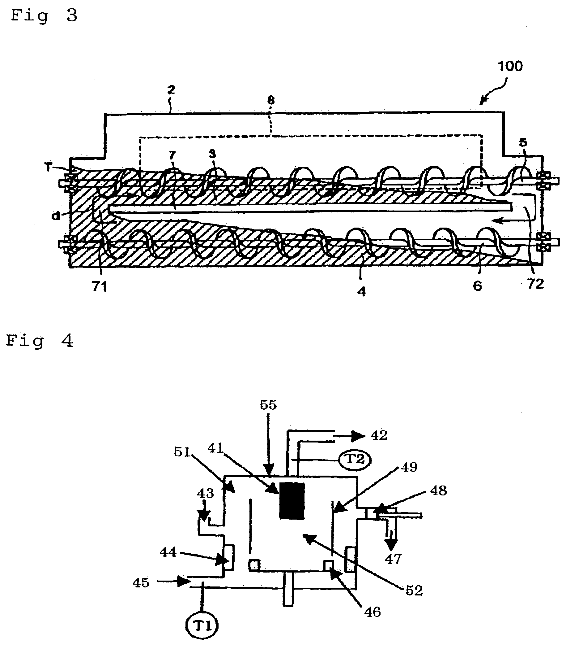
[0392] Image output and evaluation were performed in the same manner as in Example 1 except the following. First, the developing unit was further reconstructed. That is, the developing unit was divided into a developing chamber for supplying a developer to a developer sleeve on an upstream side and a stirring chamber for collecting a developer passing through a developing region. Each of the developing chamber and the stirring chamber had a screw for circulating the developer. A magnet roll having a magnetic pole structure as shown in FIG. 2 was incorporated into each developing sleeve. A developer layer thickness regulating member was brought close to the developing sleeve on an upstream side as shown in FIG. 2. Further, a replenishment port (not shown) for supplying a developer for replenishment and a discharge port (not shown) for discharging an excessive developer were provided. Second, image output and evaluation were performed while the developer for replenishment (D-1)′ was r...


PUM


Abstract

The present invention relates to a developing method using a developing device including at least: a first developer bearing member arranged to be opposed to an image bearing member; and a second developer bearing member arranged on a downstream side of a rotation direction of the image bearing member with respect to the first developer bearing member, the developing method including developing a latent image formed on the image bearing member with a developer, in which: the developer is a two-component developer having toner and a magnetic carrier; and the developer has a degree of compression C in the range of 20 to 32% and a shearing stress obtained by shearing stress measurement under a consolidation load of 4.0×10⁻⁴ N/mm2 in the range of 0.5×10⁻⁴ to 2.5×10⁻⁴ N/mm2.

Description

BACKGROUND OF THE INVENTION [0001] 1. Field of the Invention [0002] The present invention relates to a developing method for developing an electrostatic latent image formed on an electrostatic latent image-bearing member such as an electrophotographic photoreceptor or an electrostatic recording derivative with a two-component developer for visualization in electrophotography. [0003] 2. Description of the Related Art [0004] Although a large number of methods have been conventionally known as electrophotography, a general method involves: using a photoconductive substance to form an electrostatic latent image on an electrostatic latent image-bearing member (a photosensitive drum) by using various means; developing the electrostatic latent image with a developer (toner) for visualization; transferring the toner image onto a transfer material such as paper as required; and fixing the toner image onto the transfer material by virtue of heat, pressure, or the like to obtain a copy. Develo...

Claims


Application Information

Patent Timeline
Patent Type & Authority Applications(United States)
IPC IPC(8): G03G9/08G03G13/08G03G15/09
CPCG03G15/0921G03G9/0821G03G15/10G03G2215/0607
Inventor OKAMOTO, NAOKIFUJIKAWA, HIROYUKIISHIGAMI, KOHSUGAHARA, NOBUYOSHIBABA, YOSHINOBUITAKURA, TAKAYUKI
Owner CANON KK
Why Eureka
Try Eureka