
System and user interface for handling a person, and method therefor

a system and user interface technology, applied in the field of handling systems, can solve the problems of system requiring an assistant to push the lift system, system necessitating a lot of space, and the lift system with electric motors still requires significant space in order to be steered around

Active Publication Date: 2006-06-29
HECARE SYST
View PDF7 Cites 37 Cited by
  • Summary
  • Abstract
  • Description
  • Claims
  • Application Information

AI Technical Summary

Benefits of technology

[0009] Hereby, it is possible to steer the handling system in an easy and natural way e.g. in limited spaces by the lifted person or an assistant. Further, the present handling system allows the person, being lifted or moved, single-handed to perform the lift or movement only with the help of the user interface. If an assistant controls the handling system the assistant may focus less on the system and more e.g. on the direction of the system and the well being of the person, being lifted or moved.
[0031] Further, the invention relates to a method of handling a person, such as lifting or moving the person from a first position to another, with a handling system including at least one user interface, said method comprises the following steps: lifting the person by a lifting device of said handling system, moving the person in said handling system, directly or indirectly controlling the direction of each of the wheels of said handling system by said at least one user interface, in which the control is performed by the person being handled or an assistant. Hereby is an advantageous embodiment of the invention achieved.

Problems solved by technology

The system has the significant disadvantage of requiring an assistant to push the lift system.
Further, the system necessitates a lot of space in order to be steered around in narrow spaces e.g. in a person's bed or living room.
The lift systems with electric motors still require significant space in order to be steered around.
With the electric drive and supporting user interface the space requirement are often higher than with manually driven systems due to limitations and less precision in the user interface.

Method used


Image

  • System and user interface for handling a person, and method therefor
  • System and user interface for handling a person, and method therefor
  • System and user interface for handling a person, and method therefor

Examples


Embodiment Construction

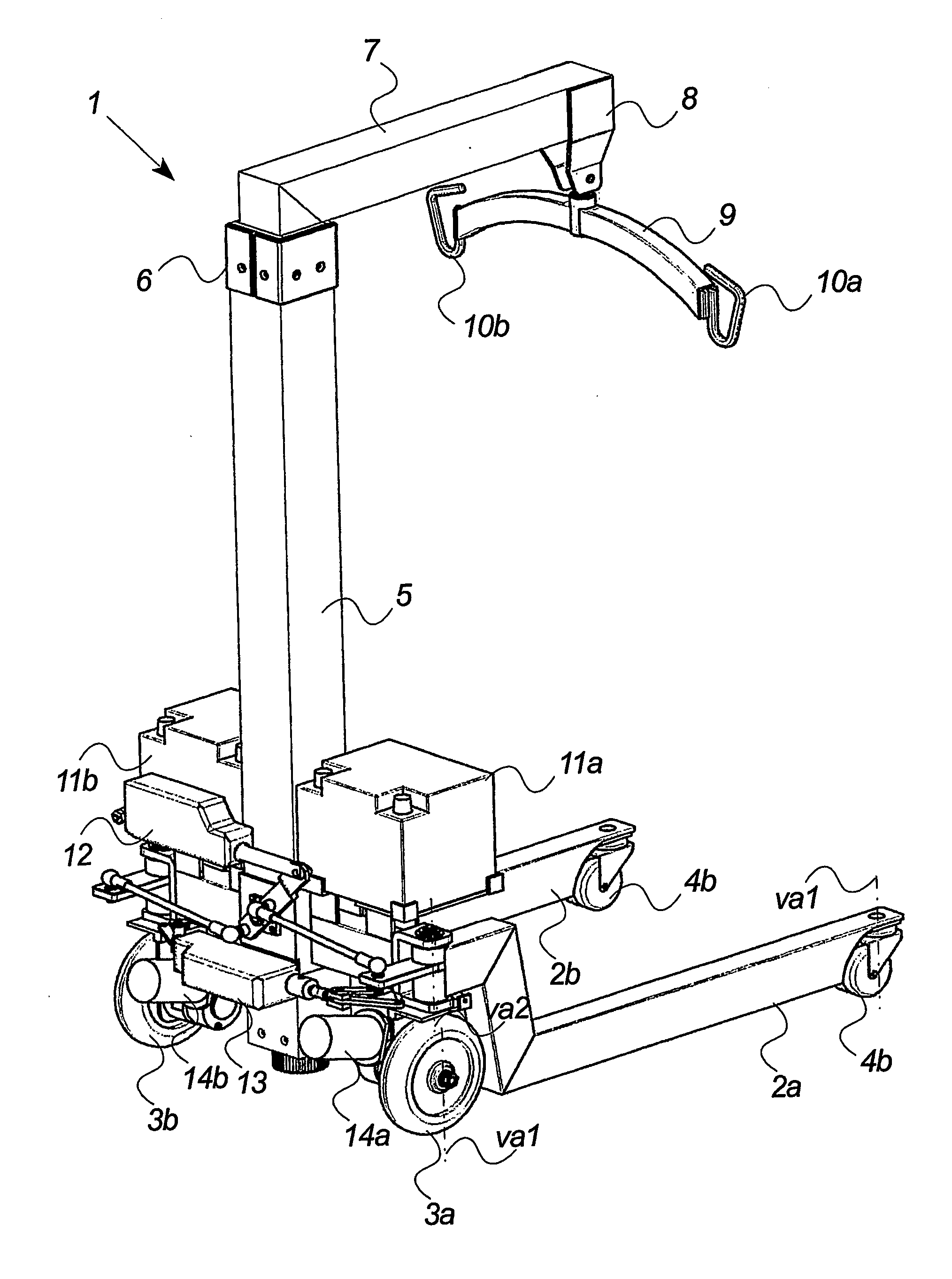
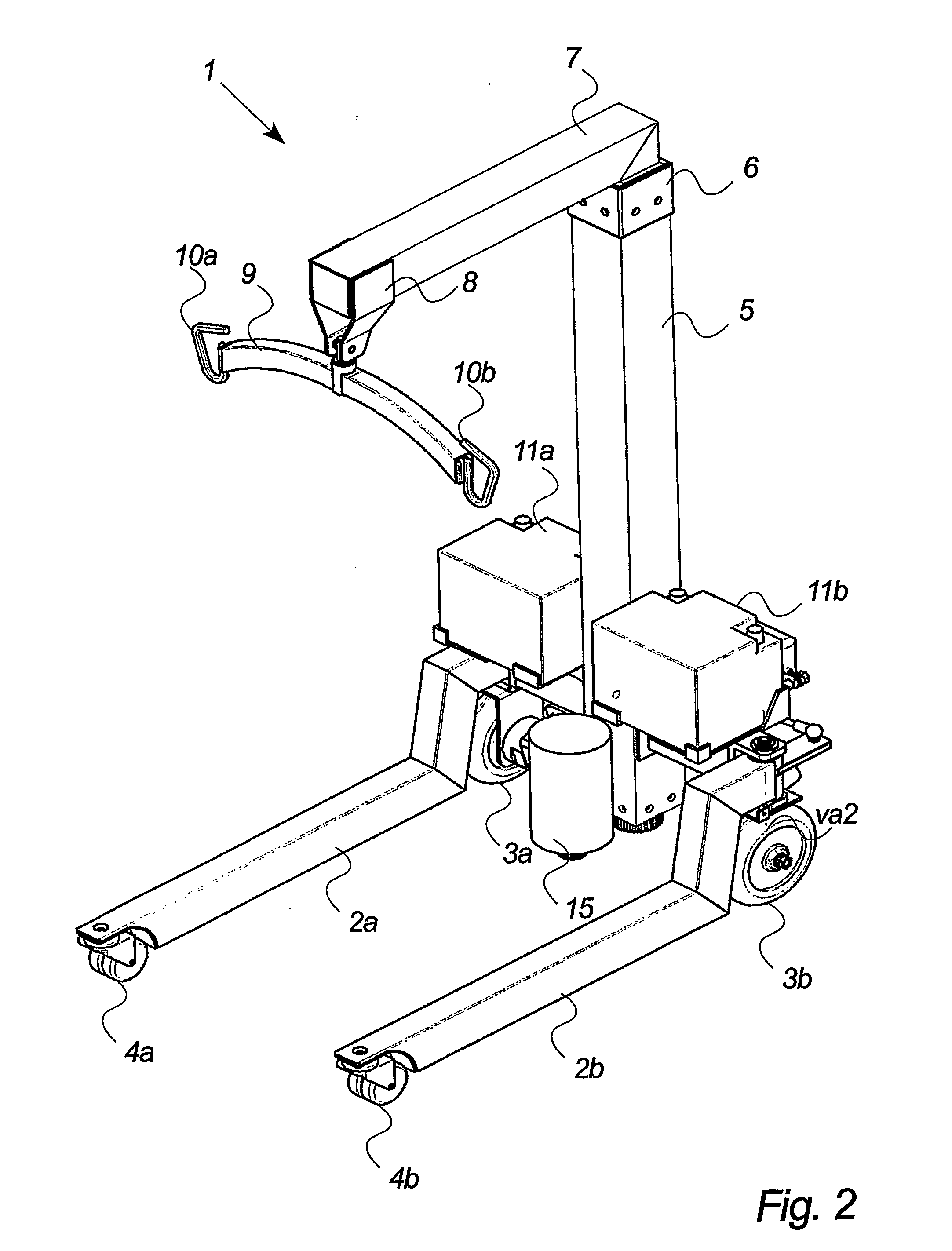
[0044]FIG. 1 illustrates a handling system 1 for a (permanently or temporarily) disabled person such as a bedridden person that needs lifting and movement to a second position e.g. a chair and vice versa. The handling system of the figure is seen from the rear and substantially in a forward moving direction of the system.

[0045] The handling system 1 comprises a left and right base frame part 2a, 2b pivotally connected in one end to a left and right centre arm 18a, 18b. The pivoting movement of each base frame part is established around a vertical axle va2. The frame parts and the centre arms together form the horizontal part of a base frame and are shaped as a fork in which each part extends from one end of a centre arm. The other end of the centre arms is connected to opposite sides of a vertical base frame 5 at a lower position of the frame. The connection between the vertical base frame and the centre arms are preferably achieved by welding the parts together in order to establi...


PUM


Abstract

The invention relates to a handling system for lifting and / or moving a person from a first position to another. The system includes a frame having a base frame and a lifting frame being part of a lifting device for the person. The system also includes at least three wheels positioned in different parts of the base frame and allowing the handling system to be moved over a surface from said first position to another, and at least one user interface allowing the person or another person to control the handling system. Further, the system includes at least one of the wheels being directional controllable from the at least one user interface and each of the wheels being mounted pivotally around a vertical axle of the wheels. The invention also relates to a user interface and a method of handling a person.

Description

BACKGROUND OF THE INVENTION [0001] The present invention relates to a handling system for lifting and / or moving a person from a first position to another according to the preamble of claim 1, a user interface for a handling system according to the preamble of claim 15 and a method of handling a person. [0002] The available systems for lifting disabled persons usually incorporate the functionality of moving the lifted person from a position to another. [0003] The most commonly used lift system involves the use of four wheels positioned in opposite corners of a fork-shaped basic frame of the system. Some of the wheels are usually of type that directionally may move freely and thus allowing an assistant to push the lift system in a preferred direction. [0004] The system has the significant disadvantage of requiring an assistant to push the lift system. Further, the system necessitates a lot of space in order to be steered around in narrow spaces e.g. in a person's bed or living room. [...

Claims


Application Information

Patent Timeline
Patent Type & Authority Applications(United States)
IPC IPC(8): A61G7/10B60B33/00B62D7/02
CPCA61G7/1015A61G7/1019A61G7/1046A61G7/1048A61G7/1053A61G7/1061A61G7/1067A61G7/1076A61G2007/0527A61G2200/34A61G2203/12A61G2203/32B60B33/0002B60B33/0005B60B33/0018B60B33/0028B60B33/0039B60B33/0042B60B33/0049B60B33/0057B60B33/0068B60B33/0084B60B33/0092B60B35/1036B60B35/109B60B35/14B62D7/02A61G7/0527
Inventor GRAMKOW, ASGERFAERGEMANN, THOMASJENSEN, THOMAS MORTHORST
Owner HECARE SYST
Features
  • Generate Ideas
  • Intellectual Property
  • Life Sciences
  • Materials
  • Tech Scout
  • Unparalleled Data Quality
  • Higher Quality Content
  • 60% Fewer Hallucinations
Learn More