Tri-axial bending load testing jig

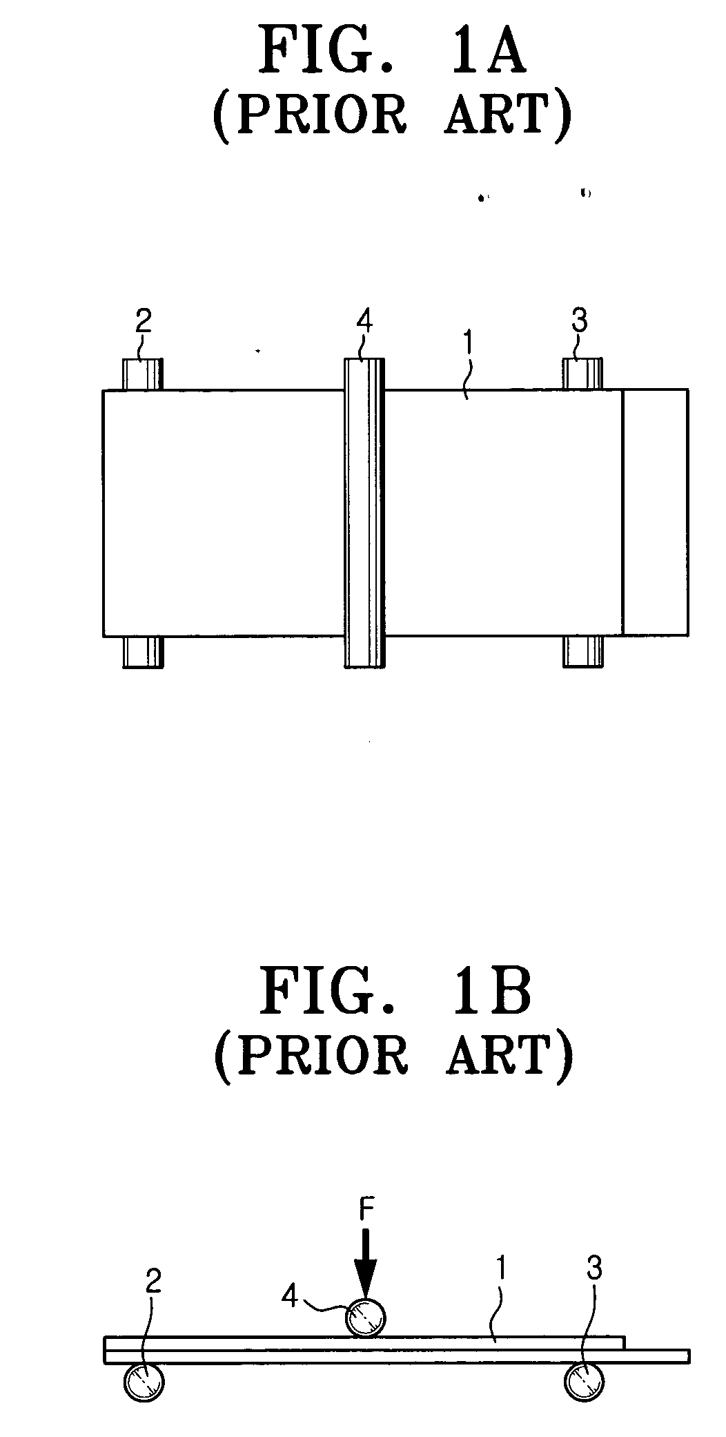
a technology of load testing and bending, which is applied in the direction of measurement devices, instruments, scientific instruments, etc., can solve the problems of elongating the working time, lcd panels of diverse sizes cannot be adaptively and accurately measured, and the device for guiding the lcd panel b>1/b> onto the supporting axes b>2/b> and b>3/b> is not dedicatedly provided, so as to achiev

Inactive Publication Date: 2006-06-29
SAMSUNG ELECTRONICS CO LTD
View PDF0 Cites 31 Cited by
  • Summary
  • Abstract
  • Description
  • Claims
  • Application Information

AI Technical Summary

Benefits of technology

[0012] An aspect of the present invention addresses at least the above problems and/or disadvantages and provides at least the advantages described below. Accordingly, an aspect of the pre

Problems solved by technology

However, since the interval between the two supporting axes 2 and 3 is constant in the conventional tri-axial bending load testing jig, LCD panels of diverse sizes cannot be adaptively and accurately measured.
Furth

Method used


Image

  • Tri-axial bending load testing jig
  • Tri-axial bending load testing jig
  • Tri-axial bending load testing jig

Examples


Embodiment Construction

[0037] Hereinafter, certain embodiments of the present invention will be described in detail with reference to the accompanying figures.

[0038] In the following description, same drawing reference numerals are used for the same elements even in different drawings. The matters defined in the description such as a detailed construction and elements are provided to assist in a comprehensive understanding of the invention. Thus, it is apparent that the present invention can be carried out without those defined matters. Also, well-known functions or constructions are not described in detail since they would obscure the invention in unnecessary detail.

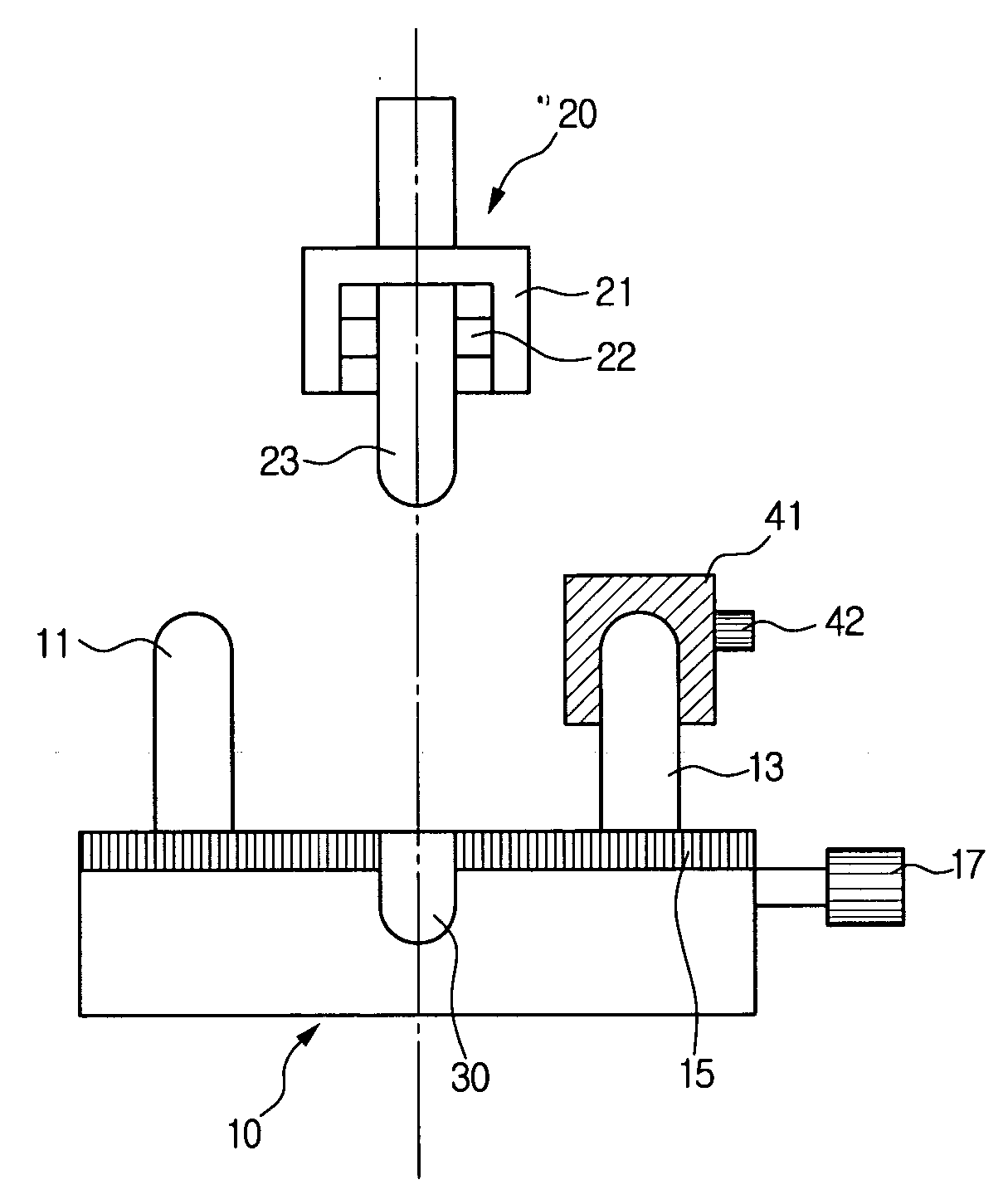
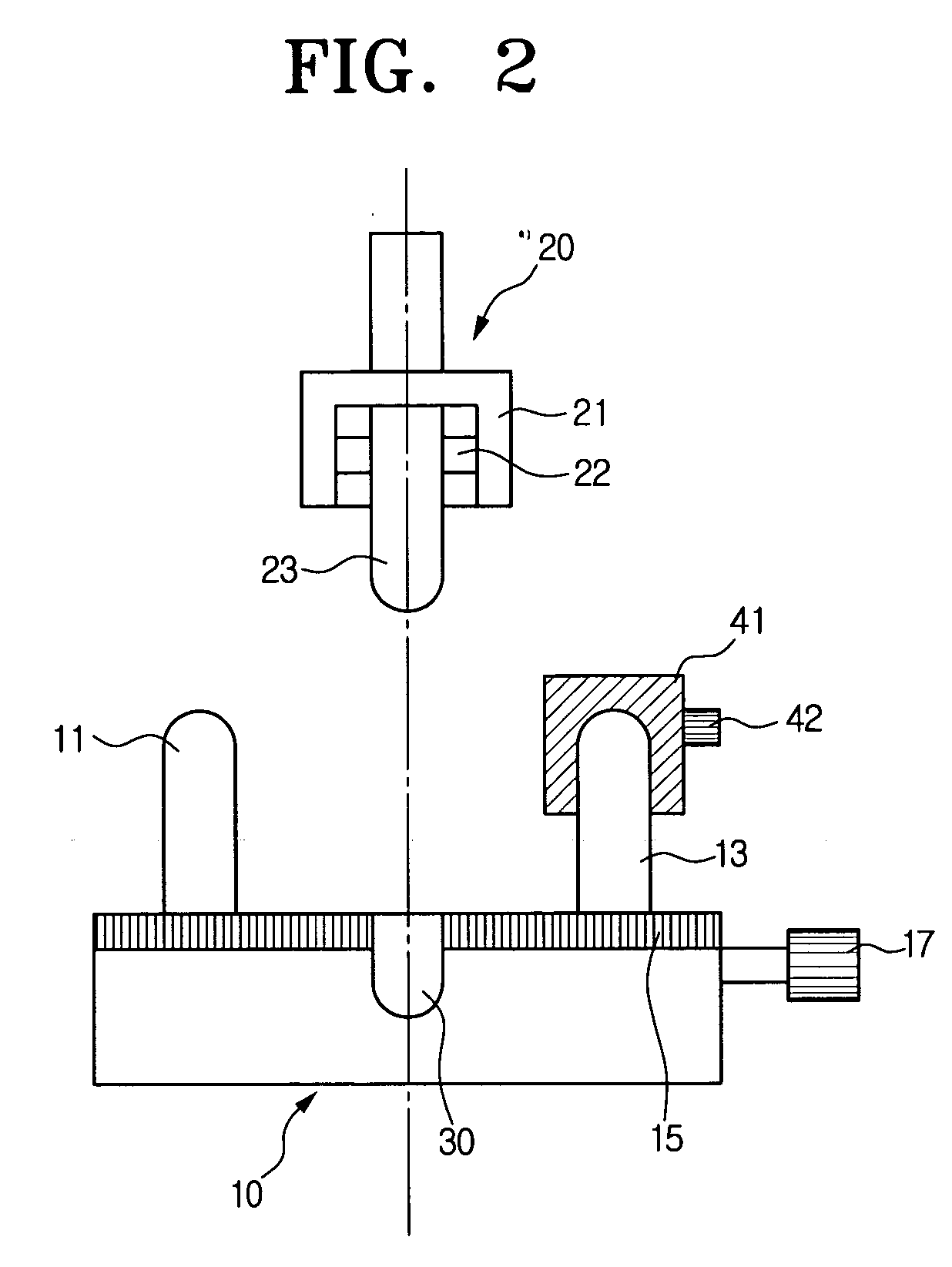
[0039] Referring to FIGS. 2 to 4, a tri-axial bending load testing jig consistent with an exemplary embodiment of the present invention, comprises a die 10, a punch 20 and a punch setting unit 30. An objective of the test in the drawings is a liquid crystal display (LCD) panel 100 as a board material.

[0040] The die 10 includes first and se...


PUM


Abstract

A tri-axial bending load testing jig includes a die including first and second supporting axes which upholds opposite sides of a board material, the first and the second supporting axes movable so that an interval therebetween can be adjusted according to a size of the board material, a punch mounted at an upper part of the die movable in a vertical direction to press down a center portion of the board material, a punch setting unit formed in the center of the die to set the center and parallelism of the punch with respect to the first and the second supporting axes and having a punch groove for receiving the punch at the center portion of the die, and a material positioning unit guiding a position of the board material to be put on the first and the second supporting axes, according to the size of the board material.

Description

CROSS-REFERENCE TO RELATED APPLICATIONS [0001] This application claims priority from Korean Patent Application No. 2004-112701, filed on Dec. 27, 2004 in the Korean Intellectual Property Office, the disclosure of which is incorporated herein by reference in its entirety. BACKGROUND OF THE INVENTION [0002] 1. Field of the Invention [0003] The present invention relates to a jig used for a tri-axial bending load test to measure the strength of a board material. More particularly, the present invention relates to a tri-axial load testing jig especially applicable for materials of various sizes, for example, a small-sized liquid crystal display (LCD) for a mobile phone. [0004] 2. Description of the Related Art [0005] A tri-axial bending load test measures rupture strength of a board material by putting the material on a die comprising a pair of support axes at a predetermined interval from each other, pressing a middle portion of the material by a punch and comparing a load at the point ...

Claims


Application Information

Patent Timeline
IPC IPC(8): G01N3/00
CPCG01N3/20G01N2203/0258G01N2203/0435
Inventor LEE, DONG-WOOYIM, SIN-TAEKBOOH, SEONG-WOONCHO, JIN-WOOKIM, KI-TAEKKWAK, DONG-OK
Owner SAMSUNG ELECTRONICS CO LTD
Why Eureka
Try Eureka