Throttle apparatus embedding electronic control unit therein

a technology of electronic control unit and throttle body, which is applied in the direction of engine controllers, mechanical devices, machines/engines, etc., can solve the problems of low corresponding property and general purpose property of parts, spatial restriction, and dissolve interference of connectors with other parts, so as to facilitate the insertion portion and keep waterproof performance , the effect of effectively maintaining the throttle body strength

Inactive Publication Date: 2008-09-18
NIKKI CO LTD
View PDF0 Cites 2 Cited by
  • Summary
  • Abstract
  • Description
  • Claims
  • Application Information

AI Technical Summary

Benefits of technology

[0009]The present invention is made for solving the problem as mentioned above, and an object of the present invention is to provided a throttle apparatus embedding an electronic control unit in which an exposing direction of a connector for connecting to an external portion can be easily changed in correspondence to a spatial condition of a mounting position, and an excellent general purpose property is generated.
[0011]Accordingly, in the case of mounting to a general purpose engine or the like in which a freedom of an arranging space is small, a direction of the connector can be easily set to a direction in correspondence to the spatial condition caused by the surrounding engine parts.
[0012]Further, the structure may be made such that the circuit board is formed as a symmetrical shape around the center portion thereof in the case of seeing from the plane, and is storable within the throttle body by selecting from two directions which are different at least 180 degree. Since it is generally possible to secure a space for storing the connector in almost all engines by corresponding to two directions which are different 180 degree, it is possible to easily correspond by forming by a comparatively simple shape such as a square shape or the like, and it is possible to reduce a cost.
[0014]Accordingly, it is possible to easily form the insertion portion for inserting the connector, and it is possible to form the notch in accordance with a simple procedure. Further, since the side in which the connector is not necessary is kept in the state in which the insertion portion is closed, it is possible to well keep a waterproof performance inside and outside the throttle apparatus, and it is possible to effectively maintain a strength of the throttle body.
[0015]In accordance with the present invention in which the circuit board of the electronic control unit is storable by being changed its direction into the throttle body, it is possible to easily correspond the protruding direction of the connector for connecting to the external portion in correspondence to the spatial condition of the engine mounting position, and it is possible to obtain the throttle apparatus which is extremely excellent in the general purpose property.

Problems solved by technology

However, it is often the case that a spatial restriction exists in a portion at which the throttle apparatus is positioned, at a time of mounting the general purpose engine to the individual apparatus.
However, since a connector for connecting to an external portion in an electronic control unit is determined an arranging direction on the basis of a terminal position of a circuit board embedded in the throttle body, and protrudes to an outer side largely from an outer wall of the throttle body, it is impossible to dissolve an interference of the connector with the other parts of the engine even if the throttle apparatus is made compact.
However, in this electronic control unit, a protruding direction of the connector is limited to one direction on the same plane in the throttle apparatus, and a position is changed within a width of the connector.
Accordingly, in order to arrange the connector 32 in a lower side of an intake manifold 61 in an opposite side having a sufficient space, in FIG. 4B, there can be considered to change the structure of the throttle body 40 and the internal electronic control unit, however, a corresponding property and a general purpose property of the parts become low in these cases, and an increase of a cost is caused.

Method used


Image

  • Throttle apparatus embedding electronic control unit therein
  • Throttle apparatus embedding electronic control unit therein
  • Throttle apparatus embedding electronic control unit therein

Examples


Embodiment Construction

[0024]A description will be given of a best mode for carrying out the present invention with reference to the accompanying drawings.

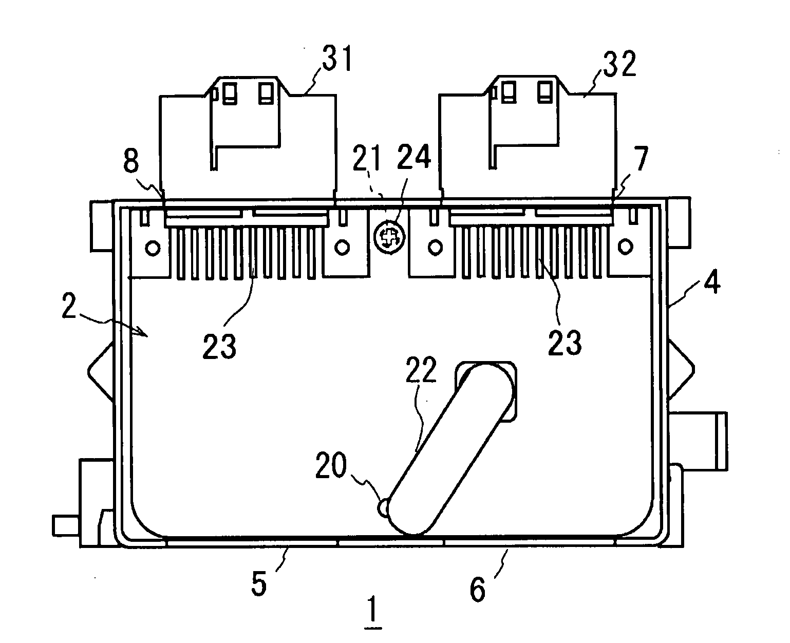
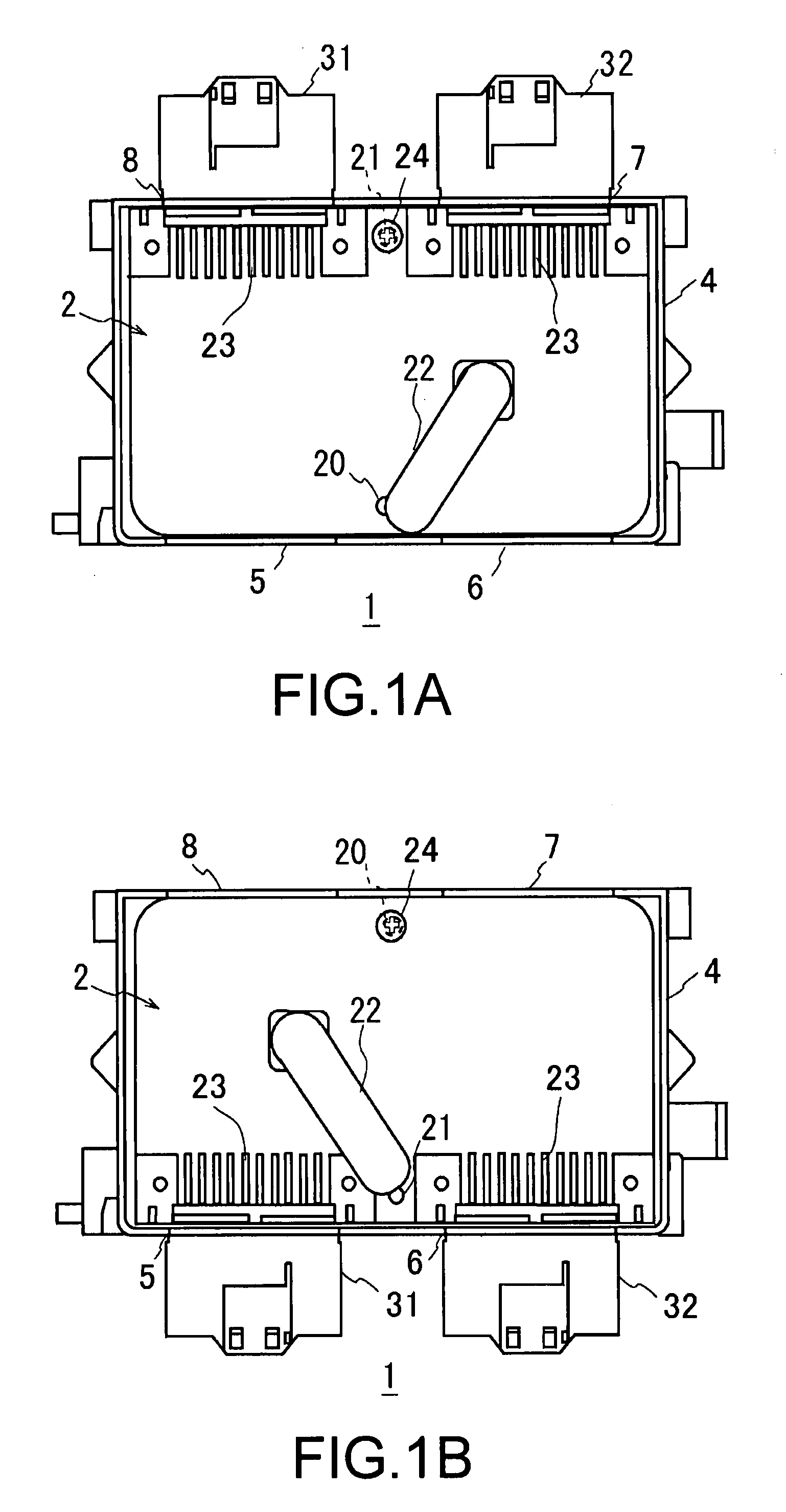
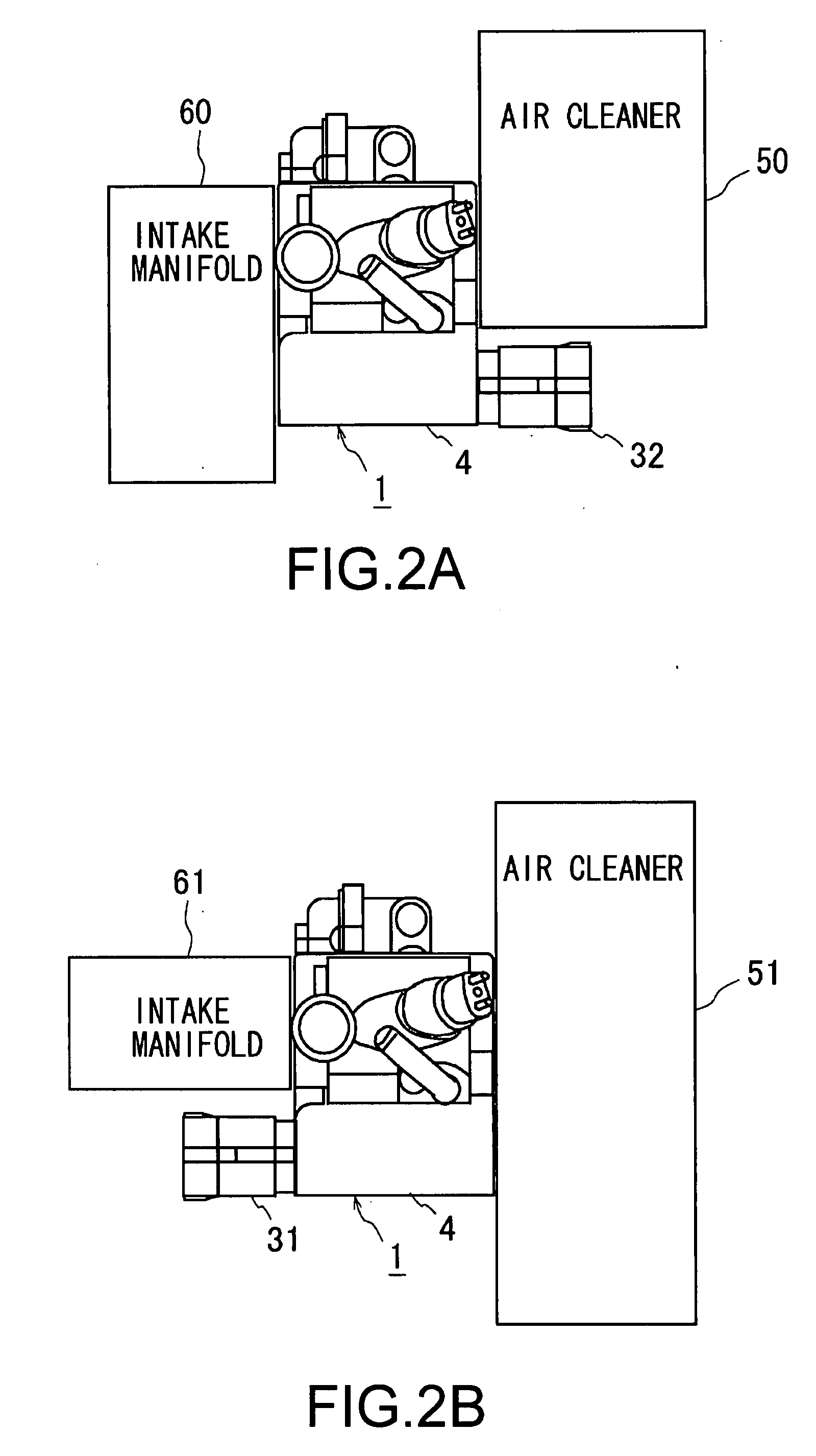
[0025]FIGS. 1A and 1B show a mounting state of a circuit board 2 serving as an electronic control unit to a throttle body 4, in a throttle apparatus 1 in accordance with the present embodiment. The throttle apparatus 1 is structured such as to regulate an intake air amount in a general purpose engine, however, is structured such as to mount a fuel injection valve (not shown) thereto, and embed the circuit board 2 corresponding to an electronic control unit therein, thereby automatically executing various controls.

[0026]Further, the circuit board 2 is characterized in that the circuit board 2 is formed approximately in a rectangular shape in a plan view, has a symmetrical outline around a center portion thereof, can be installed in a throttle body 4 by selecting both directions comprising a state in FIG. 1A and a state in FIG. 1B, and can select directio...


PUM


Abstract

A throttle apparatus embedding an electronic control unit in which a circuit board of the electronic control unit is embedded within a throttle body and a connector for connecting to an external portion connected to a terminal provided in the circuit board protrudes from an outer wall of the throttle body in a direction approximately along a terminal side of the circuit board surface from one side line of the circuit board, wherein the circuit board is storable within the throttle body by selecting an optional mounting direction from at least two or more directions having different angles on the same plane around a center portion of the circuit board, and an insertion portion capable of protruding the connector to an external portion through an outer wall of the throttle body is provided at each of corresponding positions of the outer wall.

Description

BACKGROUND OF THE INVENTION[0001]1. Field of the Invention[0002]The present invention relates to a throttle apparatus embedding an electronic control unit therein, and more particularly to a throttle apparatus of an engine, in which an electronic control unit is embedded within a throttle body, and a connector for connecting to an external portion is exposed to an outer portion of the throttle body.[0003]2. Description of Related Art[0004]In a fuel injection control system mounted to an engine having a comparatively compact and simple structure such as a general purpose engine or the like, there has been widely generalized a structure in which a fuel injection valve, an electronic control unit and the like are integrated with a throttle apparatus regulating an intake air amount. However, it is often the case that a spatial restriction exists in a portion at which the throttle apparatus is positioned, at a time of mounting the general purpose engine to the individual apparatus.[0005]...

Claims


Application Information

Patent Timeline
Patent Type & Authority Applications(United States)
IPC IPC(8): F02D11/10
CPCF02D11/10
Inventor MURAKAMI, TSUTOMU
Owner NIKKI CO LTD
Why Eureka
Try Eureka