Safety device and method for determining an overtravel in a machine

a safety device and machine technology, applied in shaping safety devices, automatic controllers, couplings, etc., can solve the problems of cnc control units generally not safe, barriers close to the leading edge not being able to stop the moving machine part in good time, and short overtravels, etc., to achieve cost-effective, convenient and safe determination of overtravels

Active Publication Date: 2006-06-29
PILZ (COMPANY)
View PDF4 Cites 5 Cited by
  • Summary
  • Abstract
  • Description
  • Claims
  • Application Information

AI Technical Summary

Benefits of technology

[0007] Against this background, it is an object of the present invention to provide an alternative which allow

Problems solved by technology

In the case of very slow machines, the overtravels are generally short, and the known safety device in this case only requires a few optical barriers, which are arranged at a smaller distance from the leading edge of the moving machine part.
However, in the case of high-speed machines and also in the case of machines having only simple

Method used


Image

  • Safety device and method for determining an overtravel in a machine
  • Safety device and method for determining an overtravel in a machine
  • Safety device and method for determining an overtravel in a machine

Examples


Embodiment Construction

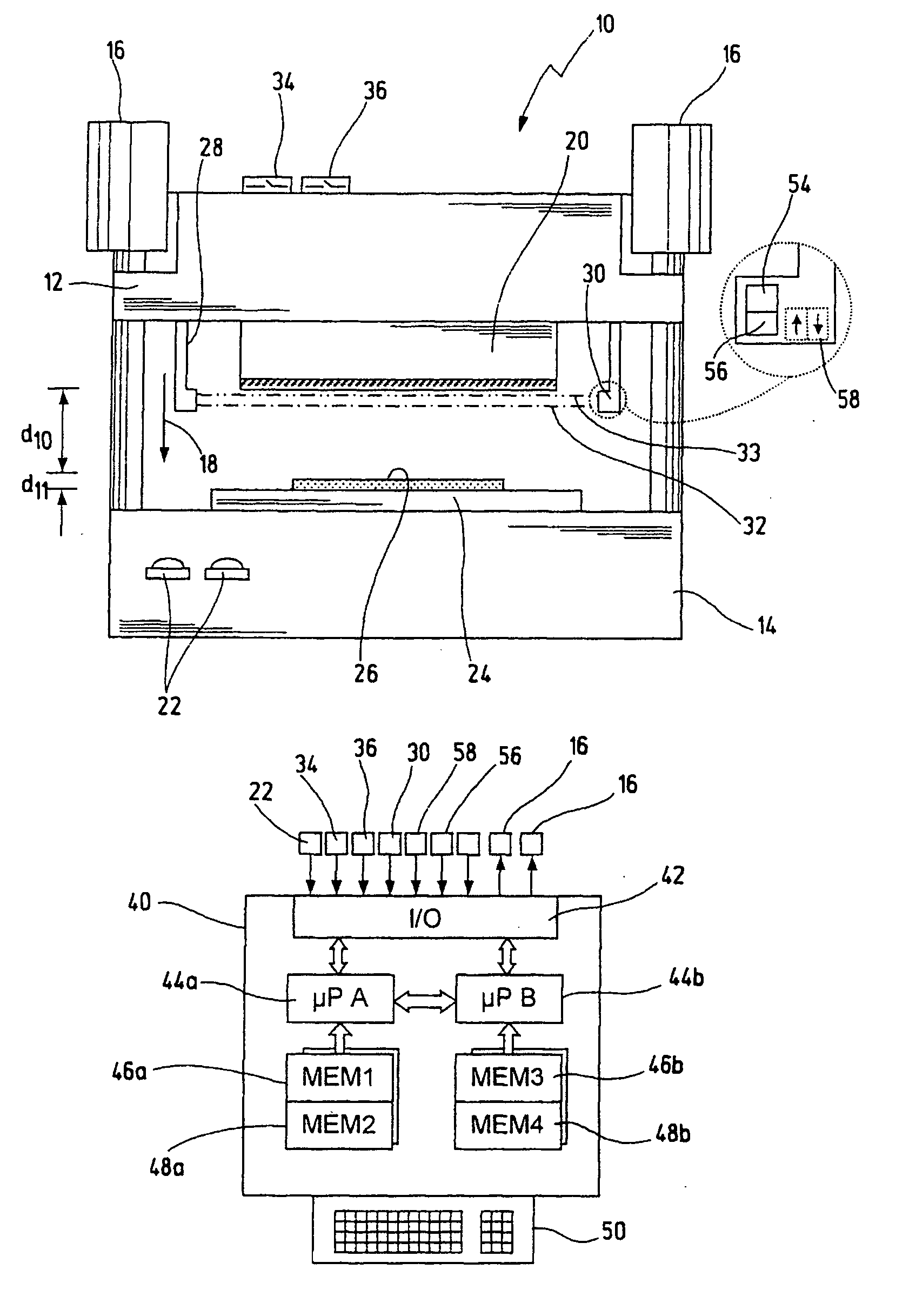
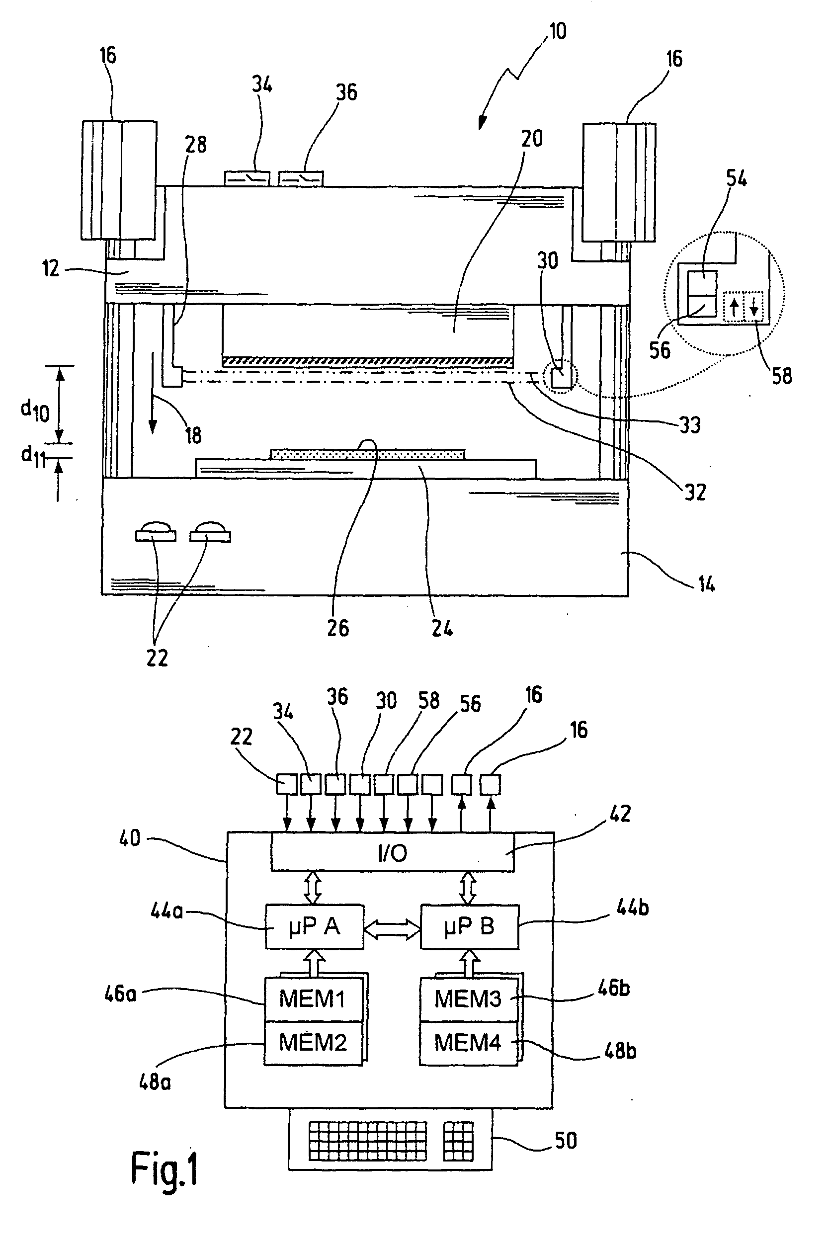
[0059] In FIG. 1, a press brake, which is a preferred machine for the new safety device, is overall given the reference numeral 10. However, it will be appreciated that the present invention can be used not only in press brakes but also in other machines, in which two machine parts carry out a working movement against each other.

[0060] The press brake 10 has an upper tool 12 and a lower tool 14. The upper tool 12 is typically the moving, first machine part in terms of the present invention, and the lower tool 14 is the second machine part. Reference numerals 16 in a simplified manner indicate two drives, by means of which the upper tool 12 can be moved towards the lower tool 14 in the direction of an arrow 18. A male die 20 is arranged on the upper tool 12. Reference numeral 22 designates a simplified illustration of a two-handed switch, which has to be actuated using two hands in order to start and carry out a working cycle of the press brake 10. As an alternative to this, the pre...


PUM


Abstract

A safety device for a machine has a first machine part for carrying out a working movement towards a second machine part. It also has at least a first and a second optical barrier moving along with the first machine part during the working movement. The first optical barrier runs ahead of the first machine part by a first distance, and the second optical barrier is arranged at a second distance from the first optical barrier. A control unit is designed to stop the working movement of the first machine part when the first optical barrier is interrupted. A test unit allows to test whether the second optical barrier has been interrupted once the first machine part has been stopped. A blocking unit serves for blocking the working movement as a function of the test result from the test unit. Using this safety device it is possible to determine an overtravel of the first machine part in a simple and reliable manner. Furthermore, an optical sensor barrier can be used to detect the position for a switchover between a rapid motion and a creep motion of the machine without requiring additional position sensors.

Description

CROSSREFERENCES TO RELATED APPLICATIONS [0001] This application claims priority from German patent application DE 10 2004 058 472.9 filed on Nov. 24, 2004. BACKGROUND OF THE INVENTION [0002] The present invention relates to a safety device for a machine, and more particularly to a safety device for a press brake, a folding bench, a stamping machine, a cutting machine or any other machine in which two machine parts are moved towards one another. However, the present invention is not restricted to these applications and can likewise be used in other machines, in which a concurrently moving protective device operating in a non-contact fashion (commonly designated as electro-sensitive protective equipment) can be used for preventing accidents. [0003] DE 202 17 426 U1, which is assigned to the present assignee and which is incorporated here by reference, discloses a safety device, which has in total eight optical barriers running ahead of a moving machine part during its working movement...

Claims


Application Information

Patent Timeline
IPC IPC(8): G06M7/00
CPCB21D55/00B30B15/288Y10T74/1406F16P3/144F16P3/14
Inventor KRIEG, MARTIN
Owner PILZ (COMPANY)
Why Eureka
Try Eureka