Drive circuit of computer system for driving a mode indicator

Inactive Publication Date: 2006-06-29
HONG FU JIN PRECISION IND (SHENZHEN) CO LTD +1
View PDF2 Cites 5 Cited by
  • Summary
  • Abstract
  • Description
  • Claims
  • Application Information

AI Technical Summary

Benefits of technology

[0008] It is simple and economical to use the drive circuit to drive the mode indicator for showing the working status of the computer syste

Problems solved by technology

It is unduly complex to use the single chip because a controlling program is required.
In addition, it is costly to use the single chip to control

Method used


Image

  • Drive circuit of computer system for driving a mode indicator
  • Drive circuit of computer system for driving a mode indicator

Examples


Example

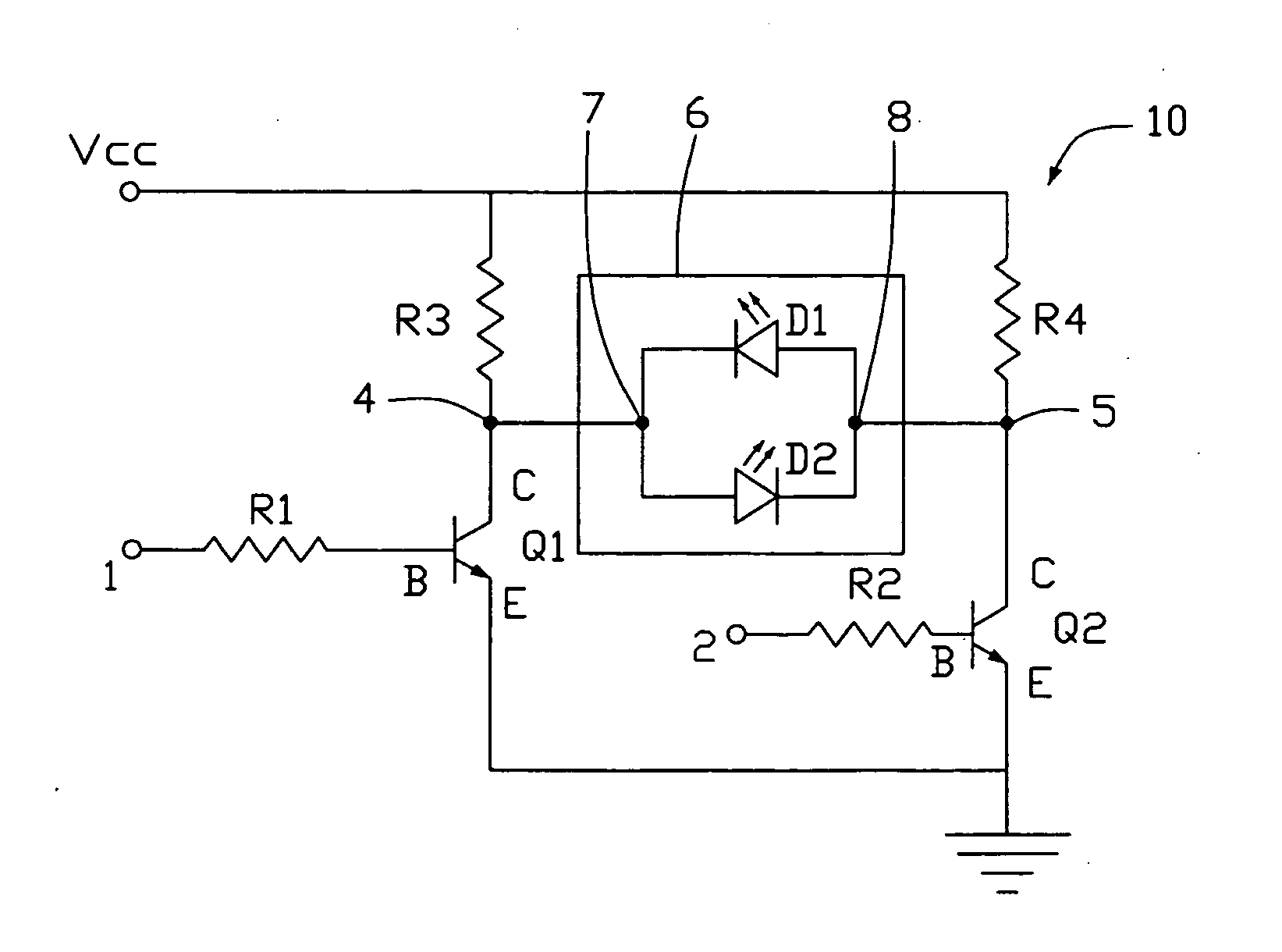
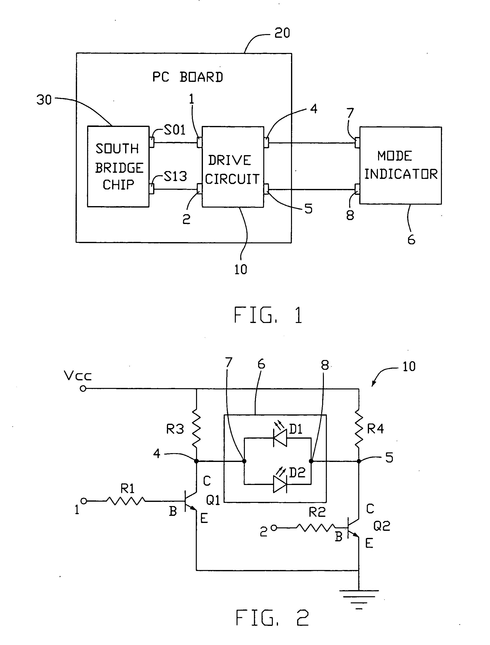
[0012] Referring to FIG. 1, a drive circuit 10 in accordance with a preferred embodiment of the present invention is shown for driving a mode indicator 6 in a computer system. The computer system includes an electronic part like a PCB 20 with a south bridge chip 30 installed thereon. The south bridge chip 30 includes a first port S01 for outputting a working signal, and a second port S13 for outputting a sleeping signal. The drive circuit 10 includes a first input end 1 connected to the first port S01, a second input end 2 connected to the second port S13, a first driving end 4, and a second driving end 5. The mode indicator 6 includes a first receiving end 7 connected to the first driving end 4, and a second receiving end 8 connected to the second driving end 5.

[0013] Referring to FIG. 2, the drive circuit 10 includes a first transistor Q1, a second transistor Q2, a power supply Vcc, a resistor R1, a resistor R2, a resistor R3, and a resistor R4. The power supply Vcc is provided w...


PUM


Abstract

A drive circuit of a computer system is for driving a mode indicator. The computer system includes a first port and a second port. The mode indicator includes a first receiving end and a second receiving end. The drive circuit includes a first input end connected to the first port, a second input end connected to the second port, a first output end connected to the first receiving end, a second output end connected to the second receiving end, a power supply, a first transistor connected between the first input end and the power supply, and a second transistor connected between the second input end and the power supply. Collectors of the first and second transistors are separately connected to the first and second output ends. The mode indicator is dichromatic and has two LEDs emitting non-matching colored light

Description

BACKGROUND OF THE INVENTION [0001] 1. Field of the Invention [0002] The present invention relates to drive circuits of computer systems, and particularly to a drive circuit which can drive a mode indicator to show a working and a sleeping status of the computer system. [0003] 2. General Background [0004] Conventionally, to save power sources, a sleeping mode is used in a computer system. Accordingly, an indicator is arranged in each of a PCB and a monitor, to show a working status or a sleeping status of the computer and the monitor. CN. Pat. No. 03236782.1 discloses a circuit controlled by a single chip to drive an indicator. The single chip uses a program to control the circuit. The indicator light is steadily on to show a working status. The indicator light flickers to show a sleeping status. [0005] However, a drive circuit of the indicator must be controlled by the single chip. It is unduly complex to use the single chip because a controlling program is required. In addition, it...

Claims


Application Information

Patent Timeline
IPC IPC(8): H03B1/00
CPCH03K19/01806
Inventor ZHOU, TONGTU, JIA-HUI
Owner HONG FU JIN PRECISION IND (SHENZHEN) CO LTD
Why Eureka
Try Eureka