Resonator filter

a resonator filter and filter technology, applied in the field of resonator filters, can solve the problems of increasing the manufacturing cost of the manufacturer, affecting the quality of the resonator, and the variability of the natural frequency of the same resonator is usually too large to keep all natural frequencies at a sufficiently right value, so as to achieve the effect of saving production costs

Inactive Publication Date: 2006-06-29
INTEL CORP
View PDF8 Cites 22 Cited by
  • Summary
  • Abstract
  • Description
  • Claims
  • Application Information

AI Technical Summary

Benefits of technology

[0011] An advantage of the invention is that when sub-bands are used it is not necessary to tune the filters separately for each sub-band in the stage of manufacture, as the sub-band can be chosen when the filter is put into use, by a single tuning motion the common control being applied. Another advantage of the invention is that the tuning mechanism consists of few parts, even only of one object, which brings savings in production costs. A further advantage of the invention is that the basic tuning of the filter can be automated, in other words it can be made without inconvenient handwork. Then an actuator and a device measuring the response of the filter are programmed to cooperate so that the tuning elements are moved programmably until an optimal response is obtained. A further advantage of the invention is that the tuning does not change in the course of time, as there are no metallic junctions between the tuning element and the rest of the structure.
is that when sub-bands are used it is not necessary to tune the filters separately for each sub-band in the stage of manufacture, as the sub-band can be chosen when the filter is put into use, by a single tuning motion the common control being applied. Another advantage of the invention is that the tuning mechanism consists of few parts, even only of one object, which brings savings in production costs. A further advantage of the invention is that the basic tuning of the filter can be automated, in other words it can be made without inconvenient handwork. Then an actuator and a device measuring the response of the filter are programmed to cooperate so that the tuning elements are moved programmably until an optimal response is obtained. A further advantage of the invention is that the tuning does not change in the course of time, as there are no metallic junctions between the tuning element and the rest of the structure.

Problems solved by technology

In series production the variation of the natural frequencies of resonators made in the same way is usually too large to keep all natural frequencies at a sufficiently right value.
A disadvantage in the use of tuning screws is that in a multi-resonator filter it may be necessary to manually turn the screws in many stages to obtain the desired frequency response.
Thus the tuning is time consuming and relatively expensive.
These facts will raise the manufacturing costs on their part.
In addition the electrical contact in the threads may deteriorate in the course of time, which results in tuning drift and in increased losses in the resonator.
Moreover, there is a risk of electric breakdown in high-power filters of the transmitting end if the point of the screw is close to the end of the inner conductor.
A disadvantage of that kind of solution is that in a multi-resonator filter it can be necessary to manually bend the tuning elements in several stages to obtain the desired frequency response.
Thus also in this case the tuning is time-consuming and relatively expensive.
Disadvantages of this solution, too, are that in a multi-resonator filter it may be necessary to manually turn the screws in many stages to obtain the desired frequency response, and that the electrical contact in the screw joint may deteriorate in the course of time.
Disadvantages of this solution, too, are that in a multi-resonator filter it may be necessary to manually turn the screws in many stages to obtain the desired frequency response.

Method used


Image

  • Resonator filter
  • Resonator filter
  • Resonator filter

Examples


Embodiment Construction

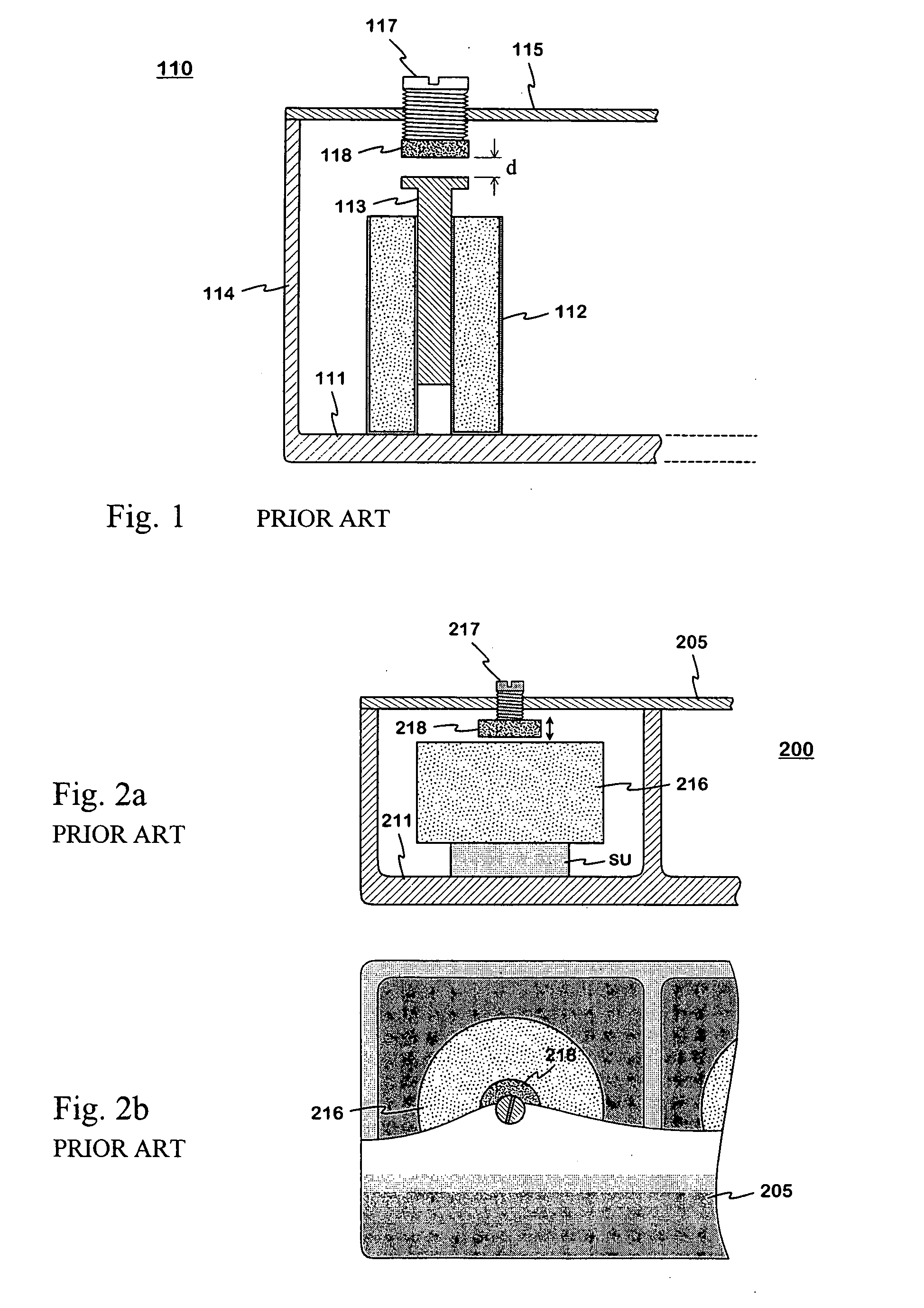
[0027]FIGS. 1 and 2 were described already in connection with the description of prior art.

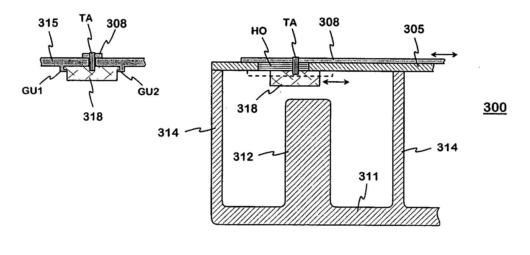
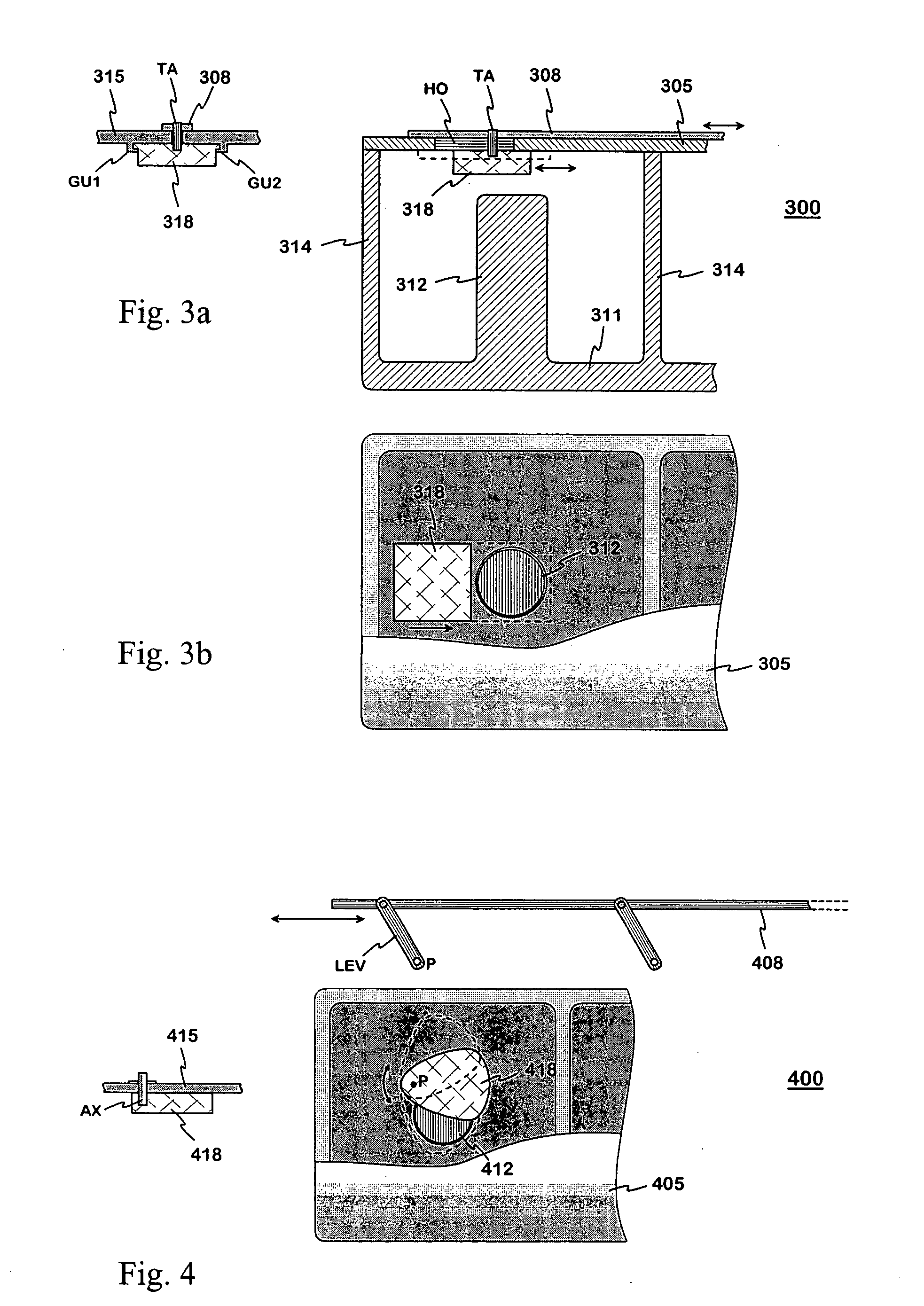
[0028]FIGS. 3a and 3b show an example of a tunable filter according to the invention. The filter 300 consists of quarter wave coaxial resonators, from which the first resonator and partly the second resonator are seen in the figure. FIG. 3a shows the structure in a longitudal section from one side. The first resonator has a bottom 311, an inner conductor 312, an outer conductor 314 and a lid 305. The tuning element 318 is a right-angled prismatic dielectric piece located at the open end of the resonator. In the vertical direction it extends from the lid about halfway to the top of the inner conductor 312. In this example the tuning element is attached to the lower surface of the resonator's lid with the aid of the guide rails GU1 and GU2 shown in the accompanying figure so that it can be moved back and forth in the horizontal plane. In order to be able to move it manually from the outside the...


PUM


Abstract

The invention relates to a tunable resonator filter. In each resonator cavity of the filter there is a movable dielectric tuning element (728; 748) to adjust the resonator's natural frequency. The tuning elements are advantageously arranged to be moved by a common control implemented by a rod (708) joining them together, to shift the filter's band through equal displacements of the natural frequencies of the resonators. When the tuning element is moved horizontally sidewards from the resonator (710; 720; 730; 740; 750; 760) axis, the electrical length and natural frequency of the resonator change. In that case, when sub-bands are used it is not necessary to tune the filters separately for each sub-band in the stage of manufacture, as the sub-band can be chosen when the filter is put into use. The tuning elements can be movable also in each resonator separately, to implement the basic tuning in connection with the manufacture of the filter. The basic tuning can be automated, in other words it can be made without inconvenient handwork.

Description

[0001] The invention relates to a filter consisting of resonators, which filter can be tuned after its manufacture. A typical application of the invention is an antenna filter in a base station. BACKGROUND OF THE INVENTION [0002] In order to obtain a frequency response of a resonator filter, which meets the specifications, it is necessary to have right coupling strengths between the resonators, and a certain resonator frequency, or natural frequency for each resonator. In series production the variation of the natural frequencies of resonators made in the same way is usually too large to keep all natural frequencies at a sufficiently right value. Therefore each resonator in each filter must be tuned individually. Here such tuning is called basic tuning. If the filter is intended to be used as a part in a system, where the transmitting and receiving bands are divided into sub-bands, then the width of the passband of the filter must equal the width of a sub-band. Further the passband ...

Claims


Application Information

Patent Timeline
Patent Type & Authority Applications(United States)
IPC IPC(8): H01P1/205H01P1/20
CPCH01P1/2053
Inventor ALA-KOJOLA, JOUNI
Owner INTEL CORP
Why Eureka
Try Eureka