High strength main tee splice

Active Publication Date: 2021-07-06
USG INTERIORS LLC
View PDF56 Cites 0 Cited by
  • Summary
  • Abstract
  • Description
  • Claims
  • Application Information

AI Technical Summary

Benefits of technology

The invention improves the strength of spliced connections in electrical grids by deliberately making the receiving depression of one splice with a larger tolerance than the end tab. This results in a substantial increase in tensile force capacity compared to previous arrangements of equivalent material thickness. This design also allows for a reduction in the thickness of the grid body material, resulting in cost savings. Additionally, the end tab has elements for aligning itself to the receiving pocket of an opposed connector in both the vertical and horizontal directions. This alignment action is assisted by horizontal alignment elements such as a lead angle and outwardly flared entrance, which provide relatively large, smooth caroming surfaces that improve the smooth functioning of the connector.

Problems solved by technology

Various known end connectors for main runners or tees can be somewhat difficult to install for numerous reasons.
Such connectors may not be self-aligning and if they have provisions for self-alignment, their performance in this regard may be marginal at best.
Smooth engagement and coupling between end connectors can be obstructed where the configuration of the connector parts have prominent surfaces or projections that interfere with the coupling advance of mating end connectors.
Thus, the technician is at least 6 feet away from the joint so that it is difficult for the technician to clearly see the end receiving pocket of the preceding runner.
Moreover, from this location, the technician cannot cup the ends to be joined in one hand to align them together.
A more subtle but sometimes more troublesome problem occurs when the end connectors are out or nearly out of dimensional tolerance due to variations in material stock, tool wear or other manufacturing conditions.
In this circumstance, the forces required to connect the ends of the runners may vary from one runner to the next so that the technician installing the grid is confounded by not knowing for sure if a good connection is being made.
Additionally, these dimensionally marginal parts can require excessive assembly force, again to the distraction or frustration of the technician.

Method used


Image

  • High strength main tee splice
  • High strength main tee splice

Examples


Embodiment Construction

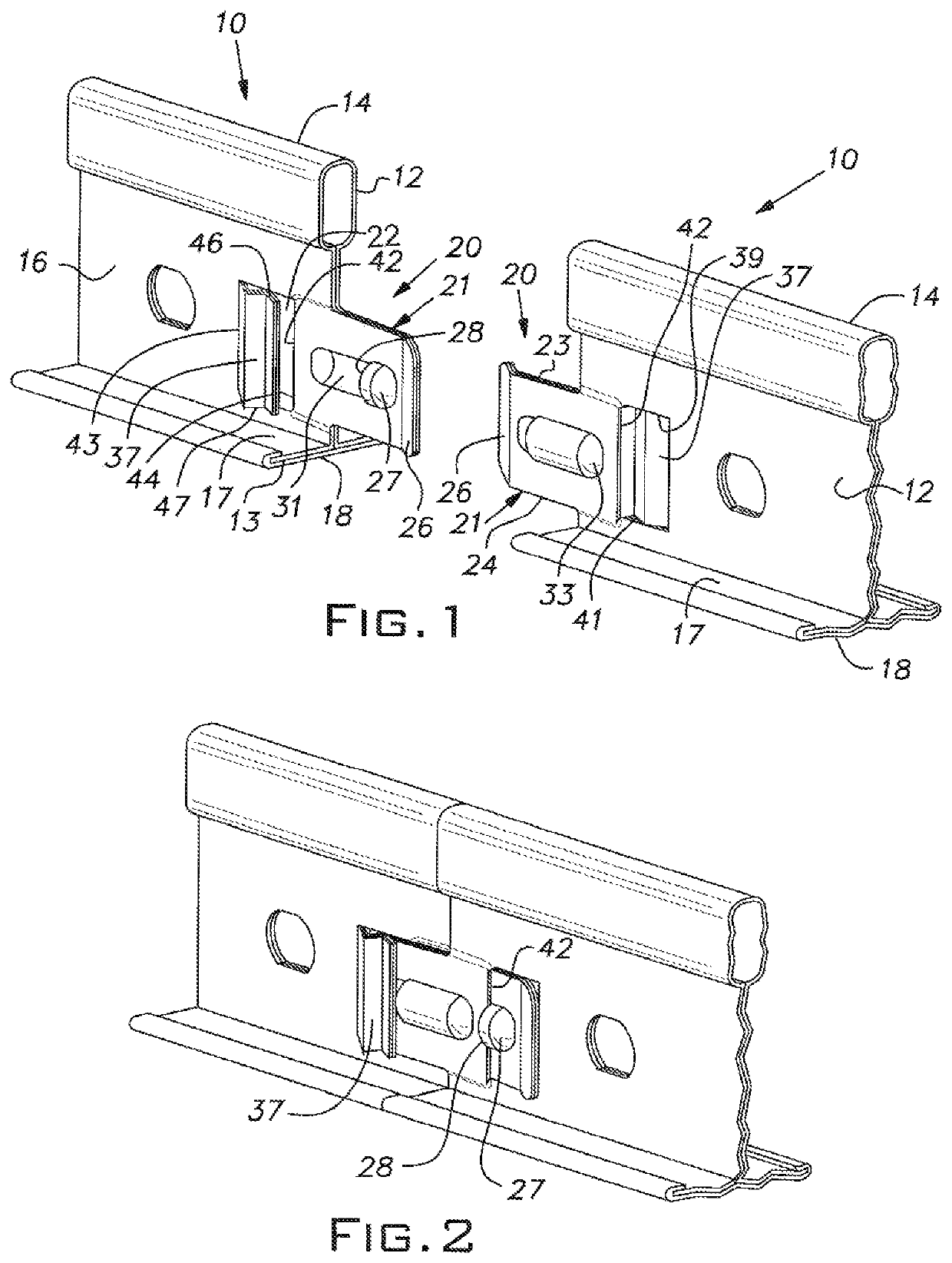
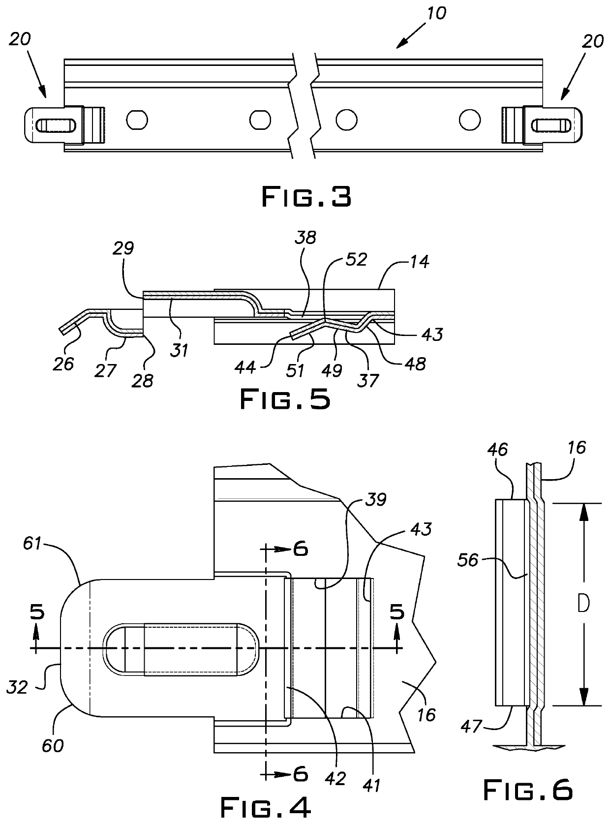
[0015]Referring now to the drawings, and in particular to FIG. 3, there is shown a main runner or tee 10 of a general type commonly used for suspended ceiling grid systems as known in the art. Typically, such main runners or tees 10 are combined with cross runners or tees (not shown) to create a suspended grid work. In the illustrated example, the main tee 10 is made of two formed metal strips 12, 13 typically of steel, although other material such as aluminum can be used. One of the strips 12 forms an upper hollow bulb 14, a double wall web 16, and oppositely extending flanges 17 all integral with one another. The strip 12 can have, for example, a thickness of 0.008 inch to 0.024 inch depending on the application. The other strip 13 lies under the flanges 17 and is wrapped around the distal edges of the flanges 17 to lock the strip 12 in its tee shape, conceal the seam between the flanges 17 and provide a smooth appearance for a lower face 18 of the tee 10; the lower face 18 of the...


PUM


Abstract

A connector for a main tee of a suspended ceiling grid that has improved tensile strength achieved by accurately proportioning an end tab and receiving depression so that full lateral abutment between these elements is obtained to assure full engagement between lock lance edges and mating stop edges.

Description

BACKGROUND OF THE INVENTION[0001]The invention relates to improvements in suspended ceiling grid components and, in particular, to end connectors for main runners or tees of such systems.PRIOR ART[0002]It is difficult to produce a main tee grid splice connector with previously known designs that is consistently easy to assemble in the field and that will result in a reliable and positive interconnection. Various known end connectors for main runners or tees can be somewhat difficult to install for numerous reasons. Such connectors may not be self-aligning and if they have provisions for self-alignment, their performance in this regard may be marginal at best. Smooth engagement and coupling between end connectors can be obstructed where the configuration of the connector parts have prominent surfaces or projections that interfere with the coupling advance of mating end connectors.[0003]Typically, main runners are 12 feet long and are installed by a technician who, during an installat...

Claims


Application Information

Patent Timeline
IPC IPC(8): E04B9/12E04B9/06E04B9/10E04B9/30E04C3/04
CPCE04B9/122E04B9/068E04B9/10E04B9/127E04B9/30E04B2009/062E04C2003/046
Inventor ZHANG, HUI
Owner USG INTERIORS LLC
Why Eureka
Try Eureka