Tensioning device

Inactive Publication Date: 2019-07-11
CHECKMATE ELEVATORING & SAFETY
View PDF0 Cites 1 Cited by
  • Summary
  • Abstract
  • Description
  • Claims
  • Application Information

AI Technical Summary

Benefits of technology

[0028]with the handle assembly in the engaged position, rotating the handle assembly

Problems solved by technology

Firstly, the worker may not be carrying the correct size spanner or socket.
Secondly, the worker may drop the spanner or socket when installing the tensioning device, which is a significant hazard when the worker is w

Method used


Image

  • Tensioning device
  • Tensioning device
  • Tensioning device

Examples


Example

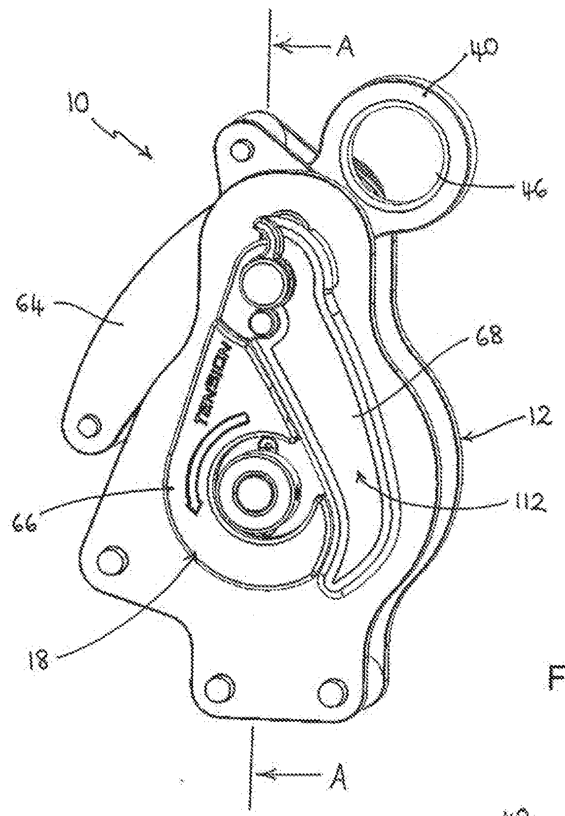
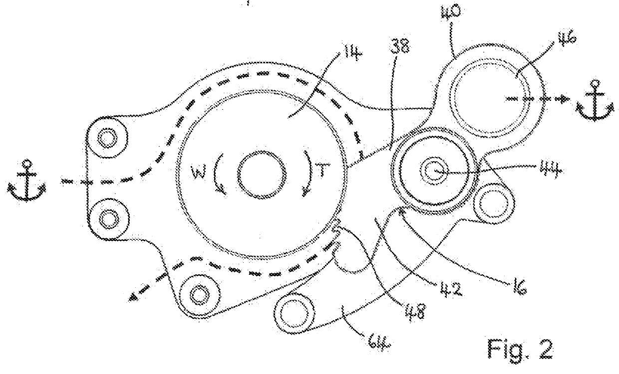
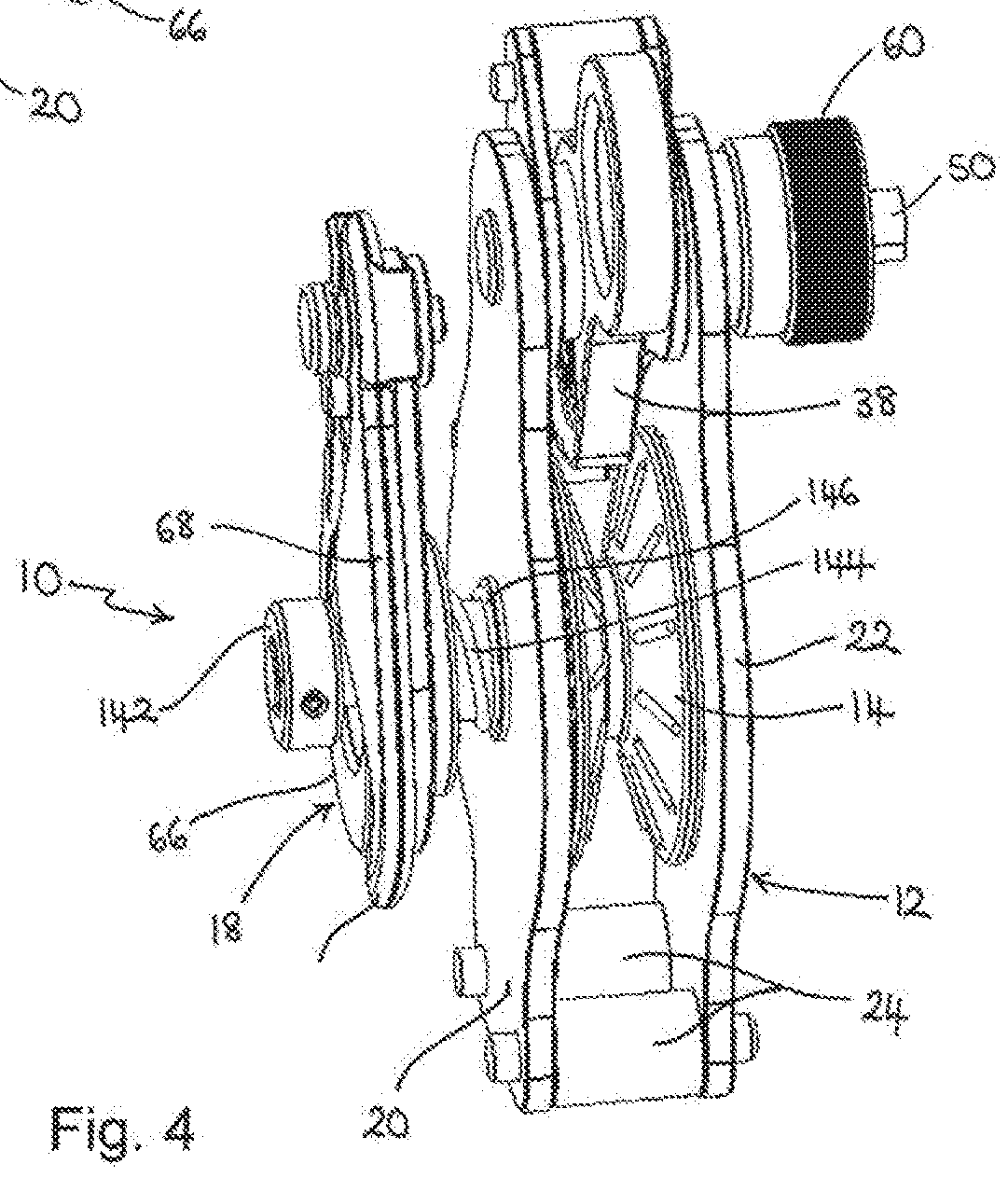
[0052]A tensioning device 10 for a horizontal lifeline is illustrated in FIGS. 1, 3 and 4. The tensioning device 10 comprises a main body 12 housing a pulley 14 and a brake mechanism 16, and a handle assembly 18 operatively connected to the pulley 14.

[0053]In use the tensioning device 10 is located and connected between an anchor point, which may comprise a building, frame or suitable stanchion, and a lifeline in the form of an elongate flexible cord or cable. In particular, and as illustrated in FIG. 2, a part of the brake mechanism 16 is connected to the anchor point by means of a suitable connector such as a shackle. The lifeline cable enters the tensioning device 10 at a first location, passes around the pulley 14 and a first, free end of the lifeline extends from the device 10 at a second location. This is illustrated by the dashed arrow in FIG. 2. The other, second end of the lifeline is connected to a second anchor point at a distance from the first anchor point. Workers work...


PUM


Abstract

One aspect relates to a tensioning device comprising a pulley including a drive spindle and a pulley wheel connected to the drive spindle, a lifeline passing, in use, around the pulley wheel; a locking member configured to engage, in use, with a part of said lifeline to prevent relative movement of the lifeline with respect to the locking member in a first direction; and a handle assembly connected to the drive spindle, the handle assembly being moveable between a first, disengaged position in which rotation of the handle assembly does not cause rotation of the drive spindle and a second, engaged position in which rotation of the handle assembly rotates the drive spindle, rotation of the drive spindle rotating the pulley to move the lifeline in a second direction relative to the locking member, thereby tensioning the lifeline.

Description

BACKGROUND[0001]This invention relates to a tensioning device to be used in a horizontal lifeline. In particular, this invention relates to a tensioning device that is installed in a temporary horizontal lifeline system.[0002]It is often necessary to install a temporary horizontal lifeline when a worker is working at height over a significant horizontal span, such that the worker may be in a location remote from an anchor point for fall arrest equipment.[0003]In these situations, a flexible line, in the form of a rope or cable, is suspended between two anchor points at the extremes of the area over which the worker will travel. A worker can then attach their personal fall arrest equipment to the horizontal lifeline to provide protection from falling from a height over the full span of the work area.[0004]It is important that the horizontal lifeline is correctly mounted and tensioned to provide the required fall arrest capability. Accordingly, it is known to attach a first end of the...

Claims


Application Information

Patent Timeline
IPC IPC(8): A62B35/00F16G11/12F16G11/10
CPCA62B35/0075F16G11/12F16G11/106A62B35/0056A62B35/0043B66D1/7415B66D3/10
Inventor NEWING, WILLIAMSTOCKBRIDGE, CHRISAUSTON, OLIVER
Owner CHECKMATE ELEVATORING & SAFETY
Why Eureka
Try Eureka