Method and apparatus for pointing the beam of a wind profiler

a beam and profiler technology, applied in the direction of instruments, antennas, reradiation, etc., can solve the problems of unreliable mechanical relays, difficult detection of possible malfunctions of relays, and expensive mechanical solutions for mechanical tilting

Inactive Publication Date: 2007-05-15
VAISALA
View PDF7 Cites 5 Cited by
  • Summary
  • Abstract
  • Description
  • Claims
  • Application Information

AI Technical Summary

Benefits of technology

[0007]It is an object of the present invention to overcome the drawbacks of the above-described techniques and to provide an entirely novel type of method and apparatus for pointing the beam of a wind profiler by tilting it in four different directions and pointing it vertically.

Problems solved by technology

Mechanical tilting requires expensive mechanical solutions.
The delay line matrix is a very practical solution but the mechanical relays are unreliable and the detection of possible malfunctions of the relays is also difficult.

Method used


Image

  • Method and apparatus for pointing the beam of a wind profiler
  • Method and apparatus for pointing the beam of a wind profiler
  • Method and apparatus for pointing the beam of a wind profiler

Examples


Embodiment Construction

[0019]Wind profilers depend upon the scattering of electromagnetic energy by minor irregularities in the index of refraction of the air.

[0020]Since these irregularities are carried by the wind, they can be used as “tracers” of the mean wind. The wind profiler transmits a beam of radio energy within a narrow band of frequencies. If the scattering volume has a component of motion toward or away from the profiler, the returned signal will be shifted in frequency by an amount proportional to the speed of this motion. By measuring this Doppler shift, one can calculate the radial velocity of the irregularities within the scattering volume and thus velocity of the wind. The radial velocity in one direction is not enough to define the wind vector; measurements in at least three directions are needed. Usually five beams are used to reduce errors due to spatial variability of the wind field.

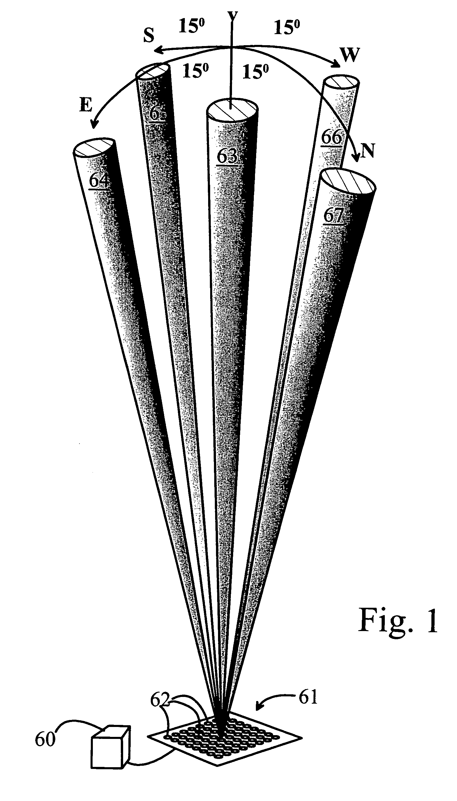
[0021]In the usual configuration as shown in FIG. 1, measurements are made using five beams: one 64 til...


PUM


Abstract

The present invention relates to a method and apparatus for pointing the beams (63–67) of a wind profiler comprising a stationary antenna matrix (61) with several individual antenna elements (62). According to the method an input signal is fed to the antenna matrix (61), and the phase of the input signal is adjusted for the individual antenna elements (62) in order to point the beam (63–67) of the profiler. In accordance with the invention separate feeder lines for each beam are used for feeding the signals to the antenna elements (62), and the phase differences between the individual antenna elements (62) are controlled with hybrid coupler elements (3, 4).

Description

BACKGROUND OF THE INVENTION[0001]1. Field of the Invention[0002]The invention relates to a method for pointing the beam of a wind profilier.[0003]The invention relates also to an apparatus for pointing the beam of a wind profiler.[0004]2. Description of Background Art[0005]In the prior art solutions the pointing is performed either mechanically tilting or with help of a delay line matrix implemented with coaxial delay elements and corresponding relays connecting the desired delay element to the antenna element.[0006]Mechanical tilting requires expensive mechanical solutions. The delay line matrix is a very practical solution but the mechanical relays are unreliable and the detection of possible malfunctions of the relays is also difficult.SUMMARY AND OBJECTS OF THE INVENTION[0007]It is an object of the present invention to overcome the drawbacks of the above-described techniques and to provide an entirely novel type of method and apparatus for pointing the beam of a wind profiler by...

Claims


Application Information

Patent Timeline
Patent Type & Authority Patents(United States)
IPC IPC(8): H01Q3/12H01Q3/02G01S13/95H01Q21/06
CPCG01S13/95H01Q21/061Y02A90/10
Inventor SALMIVAARA, JUHAHAAPANEN, PETRIKARHUNEN, PENTTI
Owner VAISALA
Why Eureka
Try Eureka