Distance calculation device and calculation program

Active Publication Date: 2006-06-29
FUJITSU LTD
View PDF9 Cites 39 Cited by
  • Summary
  • Abstract
  • Description
  • Claims
  • Application Information

AI Technical Summary

Benefits of technology

[0011] The present invention has been developed to solve the above-mentioned problems, and aims at providing a distance calculation device having the high-precision distance measuring capability by ap...

Problems solved by technology

However, in this conventional technology, only the linear distance to a traffic signal can be calculated, and there is the problem that an error occurs when the distanc...

Method used


Image

  • Distance calculation device and calculation program
  • Distance calculation device and calculation program
  • Distance calculation device and calculation program

Examples


embodiment 1

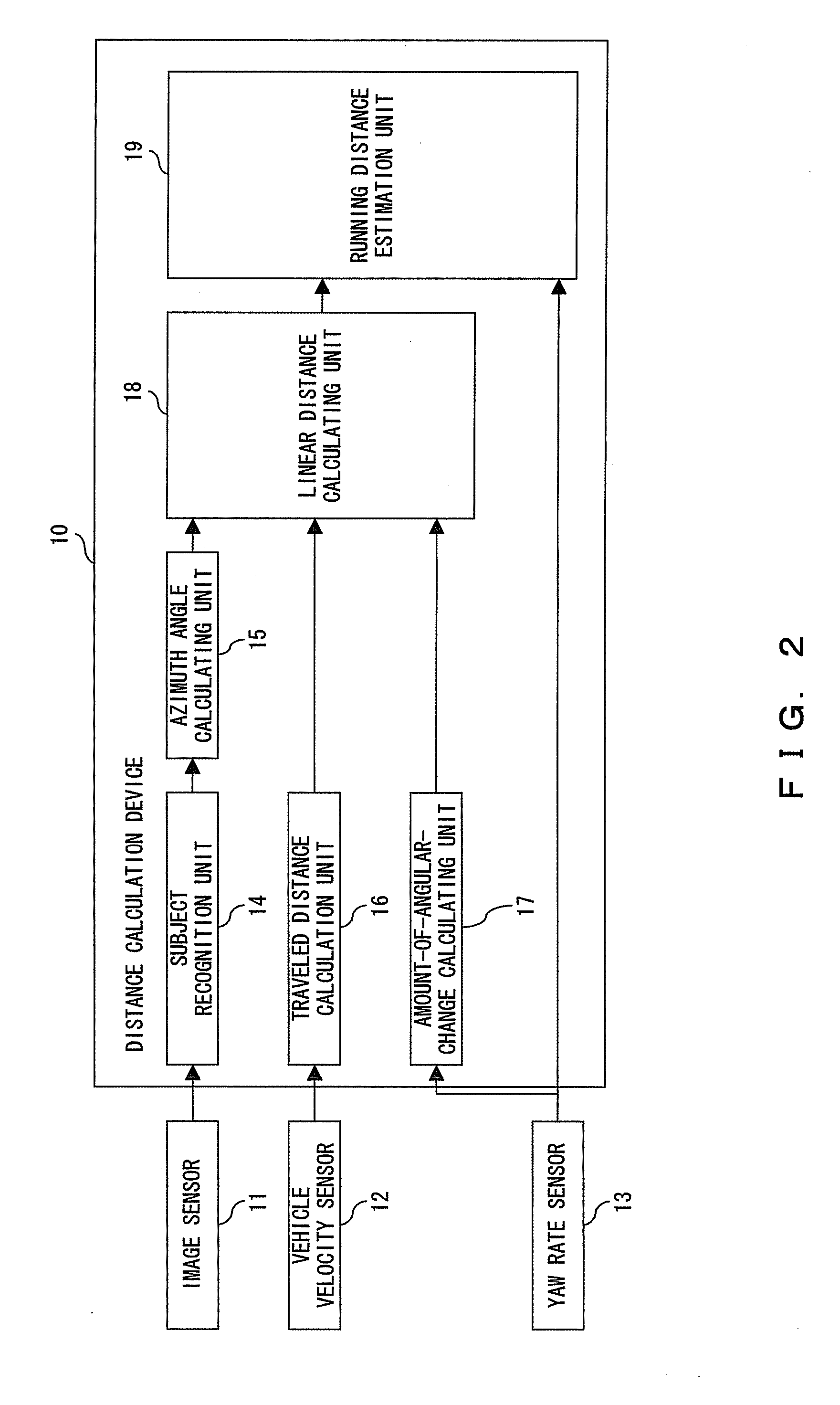
[0064]FIG. 3 is a flowchart of the entire process of calculating the distance according to the present invention. When the process is started as shown in FIG. 3, the position of a subject is recognized using the output of the image sensor 11, for example, the coordinates of the red or blue signal of a traffic signal in the image are output in step S1, the angle made by the traveling direction of a vehicle and the direction of the subject, that is, the azimuth angle, is calculated in step S2, the traveled distance of the vehicle between two points of time, that is, the traveled distance in the process interval of 100 ms, is calculated using the output of the vehicle velocity sensor 12 in step S3, and the amount of angular change on the vertical axis of the vehicle is calculated using the output of the yaw rate sensor 13 in step S4.

[0065] The processes in steps S1 to S4 can be independently performed, and the order of the processes can be changed, or the processes can be performed in ...

embodiment 3

[0095]FIG. 13 is the entire flowchart of the traveling direction distance calculating process according to the In FIG. 13, when the process is started, the subject recognition unit 14 first recognizes the position of the subject as shown in FIG. 4, the elevation angle in the direction of the subject is calculated in step 42, the traveling traveled distance is calculated in step S43, the pitching angle is calculated using the output of the inclination angle calculation unit 26 in step S44, the distance in the traveling direction is calculated as a component parallel to the traveling direction of the vehicle of the vector indicating the distance from the current position of the vehicle to the subject in step S45, thereby terminating the process.

[0096] The calculation of an inclination angle is explained below. FIGS. 14 and 15 are explanatory views of the method of calculating an inclination angle, and FIG. 16 is a flowchart of the inclination angle calculating process. FIG. 14 is an ...

embodiment 2

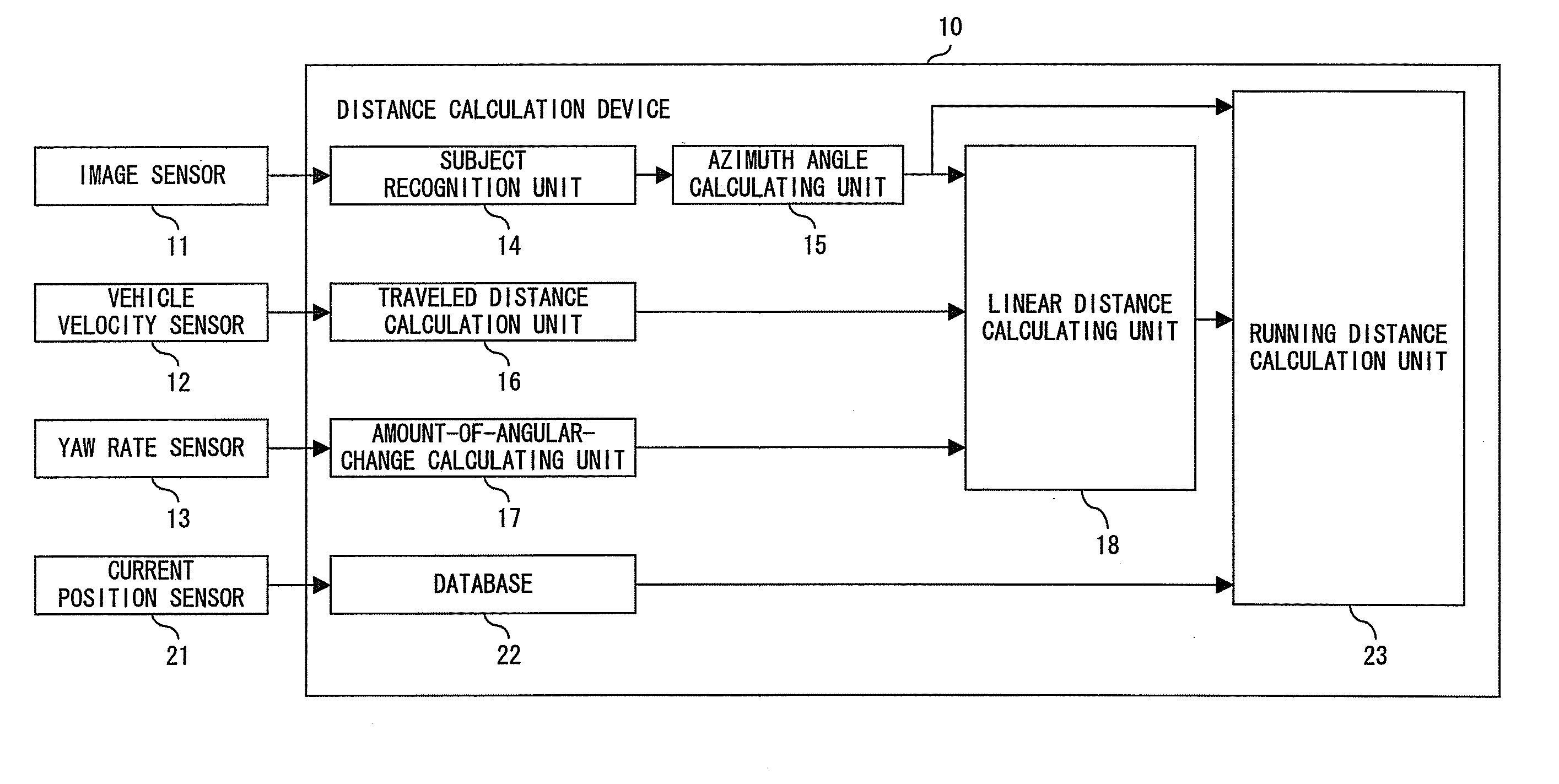
[0112] The running distance calculation unit 23 calculates the running distance using the output of the azimuth angle calculating unit 15, the output of the database 22, and the output of the traveling direction distance calculation unit 28. In the embodiment 2 shown in FIG. 9, the running distance calculation unit 23 calculates the running distance along the road to the subject using the output of the linear distance calculating unit 18, that is, the linear distance from the position of the vehicle to the subject. The process is shown in FIG. 10. The traveling direction distance calculation unit 28 shown in FIG. 22 calculates the distance X in the traveling direction of the vehicle as explained by referring to FIG. 17, and the current position of the vehicle and the linear distance to the subject is easily calculated using the output of the azimuth angle calculating unit 15, that is, ∠SA2S′. Therefore, using the linear distance, the running distance calculation unit 23 can calculat...


PUM


Abstract

It is intended to accurately calculate the distance between a movable body and a subject on the basis of various quantities of state, such as the azimuth angle between the movable body and the subject, velocity, and yaw rate. A calculation device comprises a unit for calculating the azimuth angle between movable body and a subject, a unit for calculating the distance traveled by the movable body between two points of time, a unit for calculating a change in angle in the direction of movement, and a unit for calculating the linear distance from the movable body to the subject by using the unit.

Description

CROSS REFERENCE TO RELATED APPLICATION [0001] This application is a continuation of PCT application PCT / JP2003 / 014029, which was filed on Oct. 31, 2003.BACKGROUND OF THE INVENTION [0002] 1. Field of the Invention [0003] The present invention relates to a distance calculation system between a movable body and a fixed subject, and more specifically to, for example, a distance calculation device and a calculation program for calculating the correct distance between a traveling vehicle on a road and a subject based on the amount of status of a vehicle such as the elevation angle between a traveling vehicle and a subject, an azimuth angle, the velocity and the yaw rate of a vehicle, etc. [0004] 2. Description of the Related Art [0005] The car navigation technology of guiding a driver depending on the current position of a vehicle and the destination has made much progress and has become widespread by detecting the position of a vehicle using a map database and a GPS (global positioning s...

Claims


Application Information

Patent Timeline
IPC IPC(8): G01C3/08G01S13/00G01S13/08G01P3/36G01B11/02G01C21/00G01S19/14G01C21/26G01S11/12G01S19/53
CPCG01B11/02G01C21/26G01S11/12G06T7/0042G06T2207/30236G06K9/00805G06T7/73G06V20/58
Inventor FUJII, ASAKOTAKASHIMA, TOMONOBU
Owner FUJITSU LTD
Why Eureka
Try Eureka