Optical recording method, optical recording medium, optical recording medium recording device, optical recording device, optical disk, optica disk recording/reproducing device

a recording medium and optical recording technology, applied in the field of optical recording medium optical recording device, optical recording medium recording device, etc., can solve the problems of not being practical enough, preventing marks from being properly recorded on the recording layer of the dvd medium, and needing 25 minutes to complete the writing of the 4.7-gb dvd medium

Inactive Publication Date: 2006-06-29
JVC KENWOOD CORP A CORP OF JAPAN
View PDF15 Cites 31 Cited by
  • Summary
  • Abstract
  • Description
  • Claims
  • Application Information

AI Technical Summary

Benefits of technology

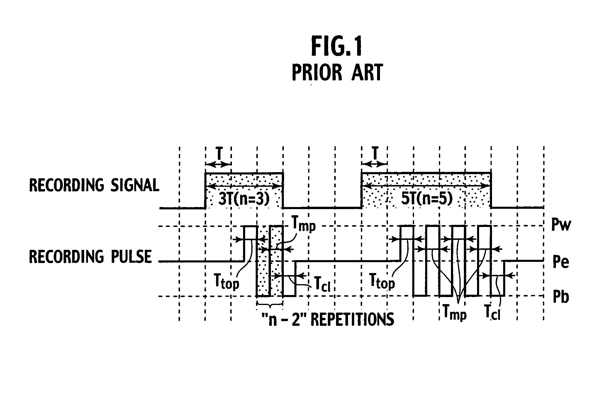
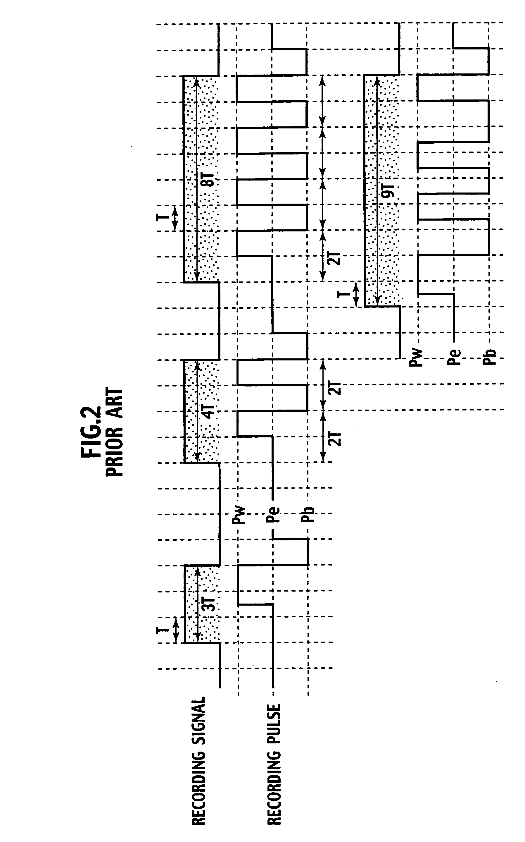
[0075] (34) There is provided an optical disk for recording information with a laser beam emitted from an optical pickup and having an information management area and an information recording area. The information management area stores recording power and recording strategy information used to store information in the information recording area, as well as linear speed information used to record information on the optical disk. The recording strategy information is used when forming, at a linear speed compatible with the optical disk, a mark corresponding to data having a length nT (n being an integer and T being a recording data clock period) by modulating the laser power of the laser beam with three values of recording power Pw, erase power Pe, and bias power Pb (where Pw>Pe>Pb). The recording strategy information includes a recording strategy employing the clock period T as a base period to be used for a low linear speed and is capable of adjusting the recording strategy according to the clock period T by changing three time sections among divided recording pulses for forming a mark, i.e., a top recording pulse width, an intermediate multi-pulse width, and a rear-end cooling power section. The recording strategy information includes a recording strategy employing a period pT obtained by dividing the frequency of the clock period by p as a base period to be used for a high linear speed and is capable of adjusting the recording strategy according to the period pT by changing three time sections among divided recording pulses for forming a mark, i.e., a bias power section before a rear-end recording pulse, a rear-end recording pulse section, and a cooling power section. The recording strategy information is beforehand stored in a plurality of recording management information sections corresponding to multiplied-speed information.
[0076] (35) There is provided an optical disk for recording information with a laser beam emitted from an optical pickup and having an information management area and an information recording area. The information management area stores recording power and recording strategy information used to store information in the information recording area, as well as linear speed information used to record information on the optical disk. The recording strategy information is used when forming, at a linear speed compatible with the optical disk, a mark corresponding to data having a length nT (n being an integer and T being a recording data clock period) by modulating the laser power of the laser beam with three values of recording power Pw, erase power Pe, and bias power Pb (where Pw>Pe>Pb). The recording strategy information includes a recording strategy employing the clock period T as a base period to be used for a low linear speed and is capable of adjusting the recording strategy according to the clock period T by changing three time sections among divided recording pulses for forming a mark, i.e., a top recording pulse width, an intermediate multi-pulse width, and a rear-end cooling power section. The recording strategy information includes a recording strategy employing a period 2T obtained by dividing the frequency of the clock period by 2 as a base period to be used for a high linear speed and is capable of adjusting the recording strategy according to the period 2T by changing, according to even or odd number data, three time sections among divided recording pulses for forming a mark, i.e., a bias power section before a rear-end recording pulse, a rear-end recording pulse section, and a cooling power section. The recording strategy information is beforehand stored in a plurality of recording management information sections corresponding to multiplied-speed information.
[0077] (36) For an optical disk for recording information with a laser beam emitted from an optical pickup and having an information management area and an information recording area, in which the information management area stores recording power and recording strategy information used to store information in the information recording area, as well as linear speed information used to record information on the optical disk, the recording strategy information is used when forming, at a linear sp

Problems solved by technology

Even at such a high multiplied speed, completely writing a 4.7-GB DVD medium needs 25 minutes, which is not sufficiently practical.
Even if the recording speed is increased, factors mentioned below prevent marks from being properly recorded on a recording layer of a DVD medium.
Consumer lasers of relatively low price used for DVD medium recorders and the like hardly provide laser strength sufficient for high-speed recording.
A second factor is that the responsibility of divided pulses (multi-pulses) of recording laser power is poor.
Then, it is difficult to apply a set heat quantity to the recording layer of a medium.
A third factor is that the material of a recording layer of a DVD medium is incapable of coping with high-speed divided pulses of recording laser power.
This is equal to a direction of making it difficult to achieve an amorphous state at a given cooling speed.
Then, the longer the length of a mark, the thinner the mark becomes, to provide an insufficient signal amplitude.
At this time, it is difficult to sufficiently extend a period of bias power.
Namely, it is difficult to secure a sufficient annealing time.
However, for 6×-speed recording on a DVD medium, the clock period T is further shortened to make it difficult to secure sufficient recording conditions for the above-mentioned optical recording method.
This results in an insufficient bias power time and an insufficie

Method used


Image

  • Optical recording method, optical recording medium, optical recording medium recording device, optical recording device, optical disk, optica disk recording/reproducing device
  • Optical recording method, optical recording medium, optical recording medium recording device, optical recording device, optical disk, optica disk recording/reproducing device
  • Optical recording method, optical recording medium, optical recording medium recording device, optical recording device, optical disk, optica disk recording/reproducing device

Examples


tenth embodiment

of Optical Recording Medium

[0167] The recording layer 3 was made by the co-spattering of a four-element single alloy target of Ge—In—Sb—Te and an Si target, to have a composition ratio of Ge1In5Sb76Te17Si1. Except this, the same optical recording medium as that of the second embodiment was prepared. Measurements similar to those of the second embodiment were carried out, and as shown in FIG. 9, characteristics substantially equivalent to those of the second embodiment were obtained for both the 4×-speed recording and 6×-speed recording.

eleventh embodiment

of Optical Recording Medium

[0168] The recording layer 3 was made by the co-spattering of a four-element single alloy target of Ge—In—Sb—Te and an Al target, to have a composition ratio of Ge1In5Sb76Te17All. Except this, the same optical recording medium as that of the second embodiment was prepared. Measurements similar to those of the second embodiment were carried out, and as shown in FIG. 9, characteristics substantially equivalent to those of the second embodiment were obtained for both the 4×-speed recording and 6×-speed recording.

twelfth embodiment

of Optical Recording Medium

[0169] The recording layer 3 was made by the co-spattering of a four-element single alloy target of Ge—In—Sb—Te and a Bi target, to have a composition ratio of Ge1In5Sb74Te16Bi2. Except this, the same optical recording medium as that of the second embodiment was prepared. Measurements similar to those of the second embodiment were carried out, and as shown in FIG. 9, characteristics substantially equivalent to those of the second embodiment were obtained for both the 4×-speed recording and 6×-speed recording.


PUM


Abstract

A mark having a length nT (n being an integer equal to or greater than 3 and T being a clock period) is formed by modulating irradiation laser power with three values of recording power Pw, erase power Pe, and bias power Pb (Pw>Pe>Pb). Constant strength periods (At) of the recording power Pw are set as AtT, A1T, . . . and AmT and constant strength periods (Bt) of the bias power Pb are set as BtT, B1T, . . . BmT, and CT (C=−1 to 3). The application of laser is divided into pulses in order of AtT, BtT, A1T, B1T, . . . , AmT, BmT, and CT (m=(n−k)/2, k=3 (if n is an odd number), or k=4 (if n is an even number)). (Here, the constant strength period of the recording power Pw for n=3, n=4, n≧5 (odd number), and n≧6 (even number) is set as At3, At4, Atod, and Atev, the constant strength period of the bias power Pb for n=3, n=4, n≧5 (odd number), and n≧6 (even number) is set as Bt3, Bt4, Btod, and Btev, and then, At3+Bt3=Atod+Btod=Am+Bm=2T and At4+Bt4=Atev+Btev=3T).

Description

TECHNICAL FIELD [0001] The present invention relates to an optical recording method; an optical recording apparatus; and an optical recording medium recording apparatus that are capable of recording information on a phase-change optical recording medium such as an optical disk and an optical card at a high multiplied speed (at least a quadruple speed); an optical recording medium used for these optical recording method, optical recording apparatus, and optical recording medium recording apparatus, recordable at a high multiplied speed; an optical disk; and an optical disk recording / reproducing apparatus for recording / reproducing information on and from the optical disk. BACKGROUND ART [0002] A conventional phase-change recording medium that is repeatedly rewritable and an optical recording method for such a medium will be explained below. [0003] For recording, a laser beam pulse is applied (emitted) to a phase-change recording medium to melt and quench a recording layer and form an ...

Claims


Application Information

Patent Timeline
IPC IPC(8): G11B20/10G11B19/00G11B5/09G11B7/0045G11B7/006
CPCG11B7/00456G11B2007/24316G11B2007/24314G11B7/0062G11B20/10222G11B2020/10898G11B7/0045G11B7/1263G11B7/0037G11B7/00454
Inventor TABATA, HIROSHIYONEHARA, KAZUOUEKI, YASUHIRO
Owner JVC KENWOOD CORP A CORP OF JAPAN
Why Eureka
Try Eureka