
Developing apparatus and image forming method

a technology of developing apparatus and developing method, applied in the field of developing apparatus, can solve the problems of its own weakness, scattering of developers, image suffering from color deviation,

Active Publication Date: 2006-06-29
CANON KK
View PDF5 Cites 16 Cited by
  • Summary
  • Abstract
  • Description
  • Claims
  • Application Information

AI Technical Summary

Benefits of technology

[0034] Thus, the primary object of the present invention is to provide a developing apparatus which employs two-component toners different in color density (two-component dark toner and two-component light toner), and which is characterized in that it forms an image which does not suffer from color deviation, by preventing the dark toner and light toner from becoming different in developmental performance.

Problems solved by technology

On the other hand, it has its own weakness.
As a result, the two-component developer changes in its properties, resulting in such problems as the formation of an image suffering from color deviation, scattering of the developer, etc.
Therefore, the two-component developer in an image forming apparatus employing a two-component developing method has to be replaced after a certain length of time.
As a result, the body of the developer in the developing apparatus remains stable in overall properties, and also, that, with the developer automatically replaced, the manual operation for replacing the developer is unnecessary.
However, the rate of carrier deterioration is dependent upon the amount by which a developing apparatus is supplied with carrier.
Therefore, as long as a conventional method for replenishing a developing apparatus with developer (carrier) is used, there is the problem that the rate of carrier deterioration substantially fluctuates in response to the amount by which a developing apparatus is supplied with toner, that is, it is affected by image ratio.
Therefore, this method is problematic in that it substantially increases an image forming apparatus in size.
However, the extent of carrier deterioration is greatly affected by the conditions under which carrier is used.
However, the greater the frequency of developer replacement, the higher the image formation cost, which is disadvantageous.
However, an image forming operation in which a substantial number of copies, which are relatively high in image ratio, are continuously outputted, is greater in the amount of toner consumption than an image forming operation in which a substantial number of copies which are relatively low in image ratio are continuously outputted.
However, as described above, the former operation is greater in the carrier replacement frequency, being therefore undesirable from the standpoint of operational cost.
This is problematic in that it results in the formation of an image suffering from color deviation.
This difference in the carrier performance, that is, the carrier's ability to give toner triboelectric charge, resulted in the formation of a defective image, that is, an image suffering from color deviation and / or fog.
However, a method such as this one also reduces the absolute amount of toner in a developing means container, degrading the developer in a developing means container, in terms of the uniformity in the toner distribution in the developing means container, which is likely to result in such a problem as the formation of a defective image, the solid areas of which are nonuniform in density, and / or suffer from density deviation.
Therefore, the above described problems occur.
Therefore, such a problem occurs that an image suffering from such an image defect that the transitional area (image area which is 40-80% in image ratio, in particular, image area which is 60% in image ratio) between an image area to be formed of light toner and an image area to be formed of dark toner has pseudo border lines and / or color deviation is formed.

Method used


Image

  • Developing apparatus and image forming method
  • Developing apparatus and image forming method
  • Developing apparatus and image forming method

Examples


embodiment 1

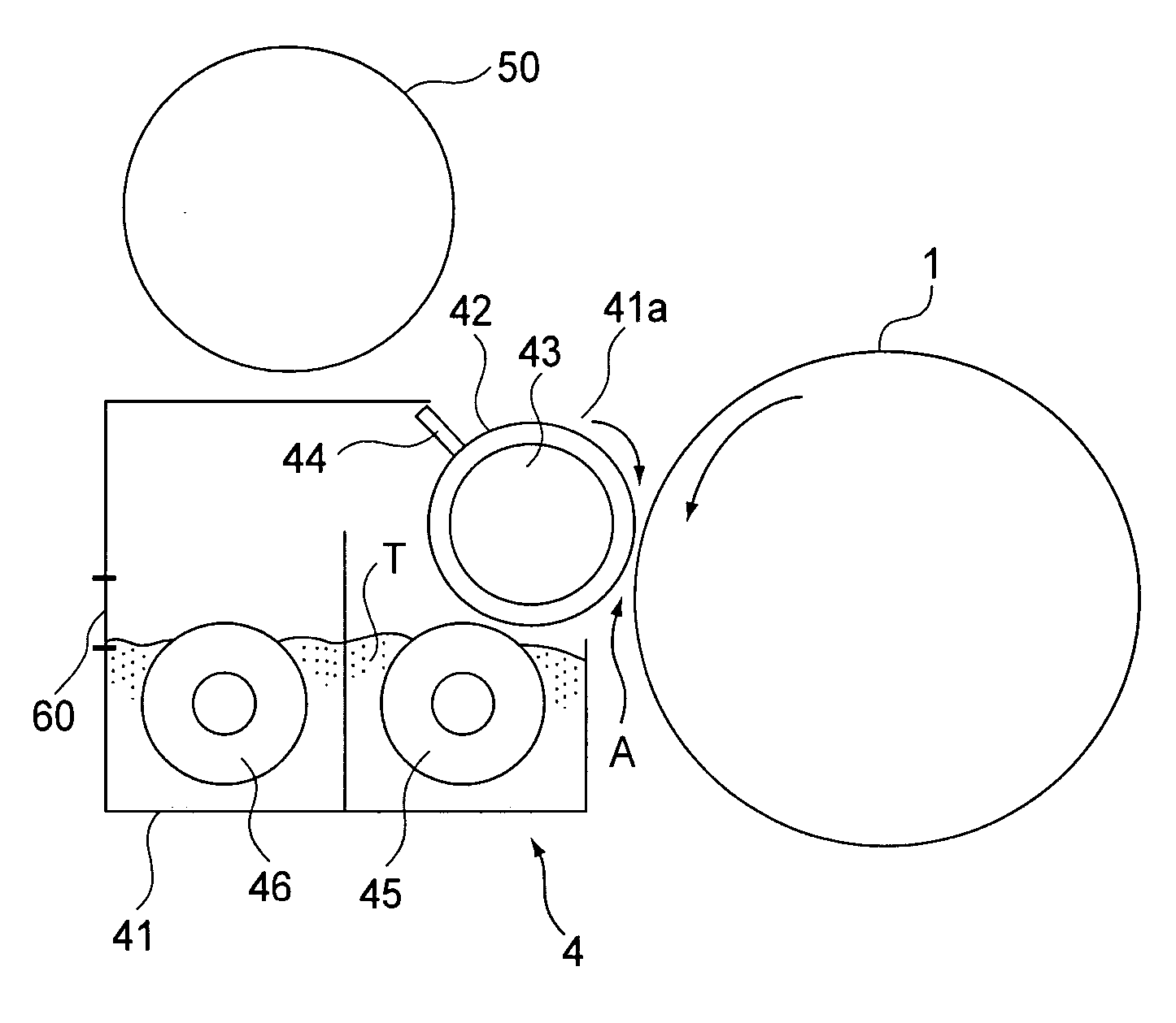
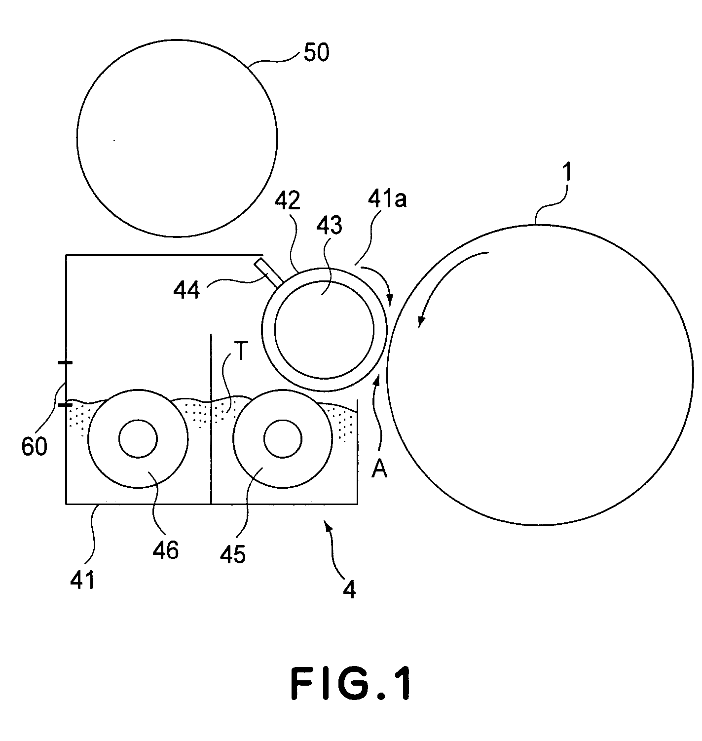
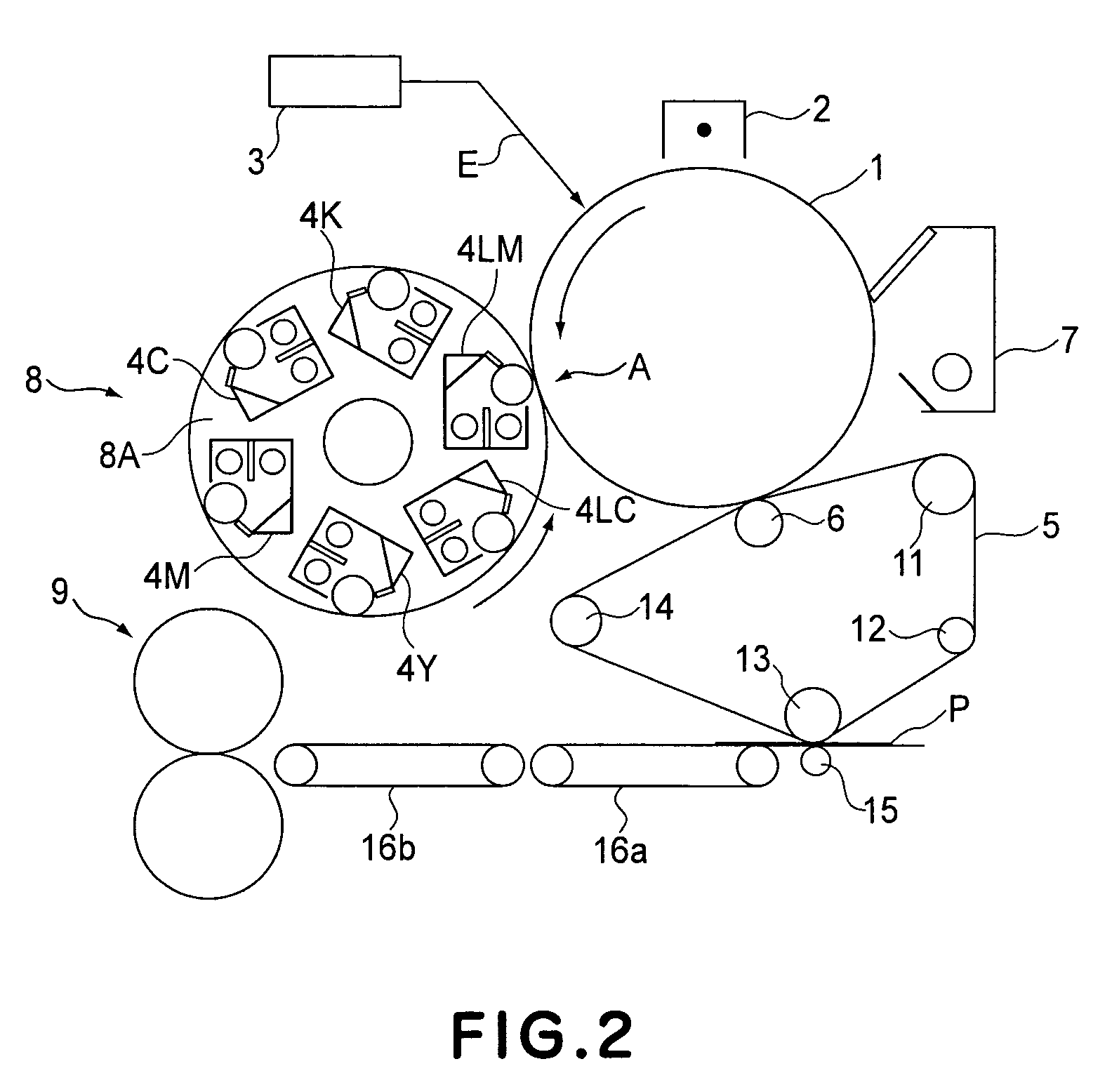
[0043]FIG. 1 shows the general structure of the developing apparatus in the first embodiment of the present invention, and FIG. 2 shows the general structure of the image forming apparatus in the first embodiment of the present invention, which employs the developing apparatus shown in FIG. 1.

[0044] First, referring to FIG. 2, the general operation of the image forming apparatus in this embodiment will be described. The image forming apparatus has an electrophotographic photosensitive member, as an image bearing member, in the form of a drum, that is, a photosensitive drum. It also has a charging device 2, an exposing apparatus 3, and a developing apparatus 8 of the rotary type, which are disposed in the adjacencies of the peripheral surface of the photosensitive drum 1. Further, the image forming apparatus has an intermediary transfer belt 5 as an intermediary transferring member, which is stretched around, being thereby suspended by, rollers 11, 12, 13, and 14, in contact with th...

embodiment 2

[0075] In this embodiment, the C / D ratio of the light toner filled in the replenishment developer hopper 50 was further reduced from 7.5% to 5%. The results of the duration tests are given in Table 2.

[0076] When the C / D ratio was 5%, the amount of the carrier in the replenishment developer was such an amount that stabilized the developer in carrier deterioration level in a duration test in which image ratio is 60%. As a result, better results than those obtained in the first embodiment were obtained; it was possible to achieve the target value of 3.1 (ΔEmax=3.1). Further, the amount by which toner could be placed in the replenishment developer hopper 50 was greater by 40 g compared to that in the developing device in accordance with the prior art. Thus, assuming that the image ratio in the average usage is 30%, the replacement intervals can be extended by a value equivalent to 150 copies of A3 size.

TABLE 2Max. Color Differencein the color difference evaluation mode60%0%60%Convent...

embodiment 3

[0080] In the field of an ordinary image forming apparatus, it is common practice to carry out the operation in which Min (Y, M, and C) (that is, minimum value among Y, M, and C) is calculated from yellow (Y), magenta (M), and cyan (C) signals, and the obtained values are used to control the process of forming an image of black toner, and the UCR operation, that is, the operation in which the amounts by which the yellow, magenta, and cyan toners are adhered to recording medium are reduced by the amount equal to the amount by which the amount by which black toner is adhered recording medium is increased.

[0081] This practice is carried out because it can reduce the amount by which cyan, magenta, and yellow toners are used. Further, it can yield such a full-color image, the black areas of which appears crisper and deeper than the black areas of a full-color image formed of three toners of primary colors, that is, the black areas made up of process black. However, if the areas of a bla...


PUM


Abstract

A developing apparatus for developing an electrostatic image with light chromatic toner and dark chromatic toner which have the same hue, the developing device includes a light color developing device for accommodating a developer containing the light chromatic toner and carrier to develop the electrostatic image; a dark color developing device for accommodating a developer containing the dark chromatic toner and carrier to develop the electrostatic image; light color developer supply container accommodating a developer containing the light chromatic toner and the carrier to be supplied to the light color developing device; and dark color developer supply container accommodating a developer containing the dark chromatic toner and the carrier to be supplied to the dark color developing device, wherein the developer in the light chromatic toner supply container and the developer in the dark chromatic toner supply container have carrier weight ratios which are different from each other.

Description

FIELD OF THE INVENTION AND RELATED ART [0001] The present invention generally relates to an image forming apparatus such as a copying machine, a printer, etc. In particular, it relates to a developing apparatus employing a two-component developing method which uses two types of developer, that is, a toner which is high in color density (which hereinafter will be referred to as dark toner), and a toner which is low in color density (which hereinafter will be referred to as light toner). It also relates to an image forming method. [0002] In the field of an image forming apparatus employing an electrophotographic image forming method, in particular, an image forming apparatus which forms a color image, a two-component developing method has been widely used, which uses a mixture of nonmagnetic and magnetic carrier, as developer. [0003] Compared to the other developing methods which are presently in use, a two-component developing method is advantageous in terms of stability in image qua...

Claims


Application Information

Patent Timeline
Patent Type & Authority Applications(United States)
IPC IPC(8): G03G15/01G03G15/08
CPCG03G15/0121G03G15/0803G03G2215/0177
Inventor HIROBE, FUMITAKENISHIHAMA, TADAYOSHINOGUCHI, AKIHIRO
Owner CANON KK
Learn More