

Gas spring ball joint and method for manufacturing the same
- Summary
- Abstract
- Description
- Claims
- Application Information
AI Technical Summary
Benefits of technology
Problems solved by technology
Method used
Image

Examples
Embodiment Construction
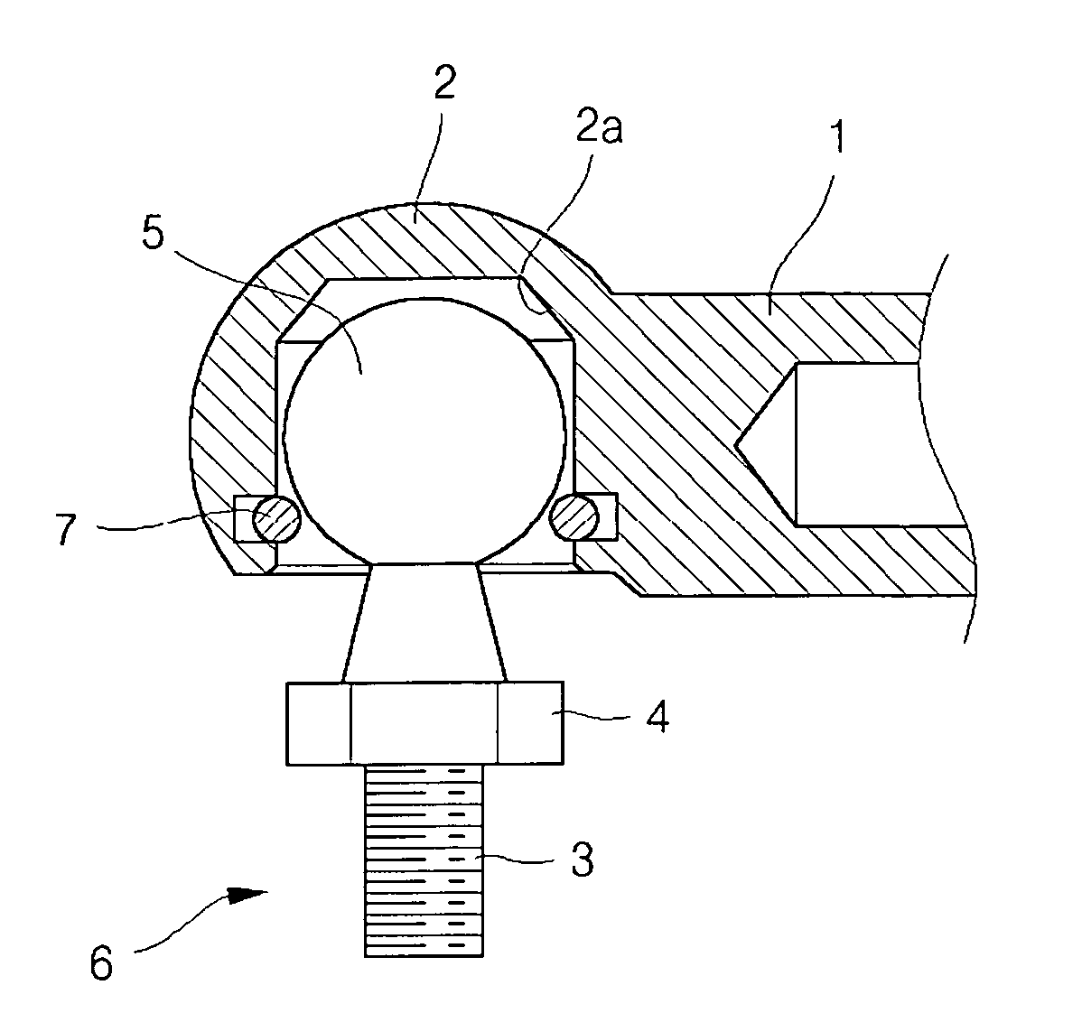
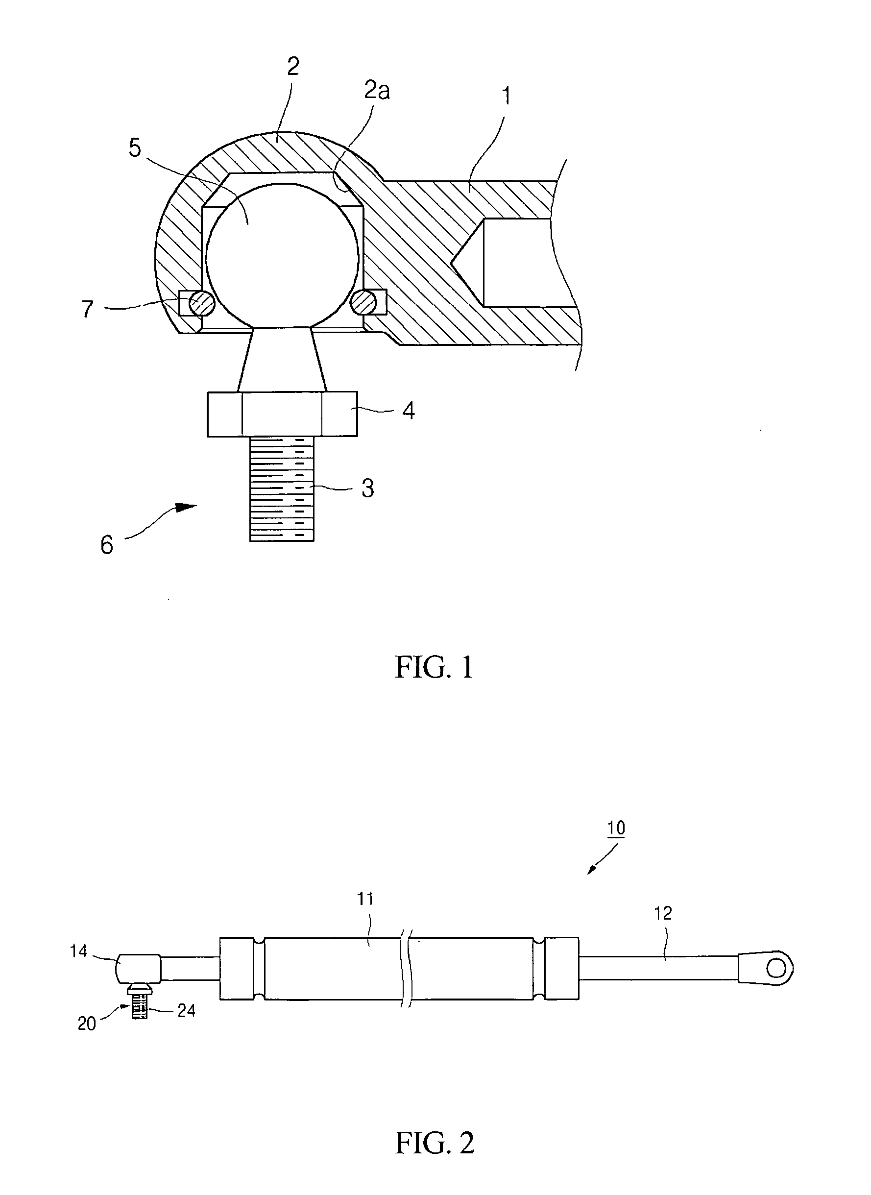
[0019] Referring to FIG. 2, a gas spring 10 configured according to an embodiment of the invention is shown. The gas spring 10 includes a cylinder 11 and a piston rod 12 protruding from the upper end of the cylinder 11. A ball stud 20 is engaged with one end of the gas spring 10, and an end socket 14 is provided as a hinge member that is part of a ball joint.
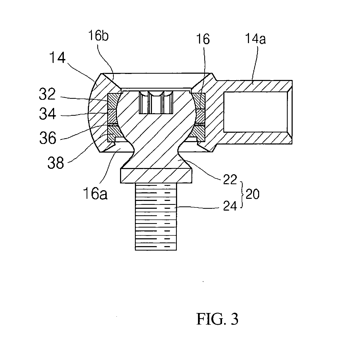
[0020] Referring to FIGS. 3 and 4, the ball joint assembly of the gas spring 10 is shown. The ball joint assembly includes a ball insertion recess 16 formed in the end socket 14. The ball joint assembly further includes a ball insertion opening 16a that is formed on one side of the ball insertion recess 16, and into which a support ball 22 of the ball stud 20 is inserted. An opened portion 16b is formed on the side opposite to the ball insertion opening 16a.
[0021] Upper and lower backup rings 32 and 34 are provided for preventing the formation of a gap between the support ball 22 and the inner surface of the ball insertion rec...
PUM
 Abstract
Description
Claims
Application Information