Feedthrough for electrical connectors

Inactive Publication Date: 2006-06-29
COCHLEAR LIMITED
View PDF16 Cites 38 Cited by
  • Summary
  • Abstract
  • Description
  • Claims
  • Application Information

AI Technical Summary

Benefits of technology

[0103] The present invention provides a method of forming a feedthrough for an implantable component comprising a relatively electrically insulative member having a plurality of relatively electrically conductive members extending therethrough. The method ensures the electrically conductive members are hermetically encased within the insulating material in a way that allows electrical connection through the feedthrough while preventing transfer of bodily fluids from outside the component into the interior of the component, as well as preventing the transfer of potentially dangerous materials from internal of the component to the surrounding tissue and body fluids.
[0104] The present invention also provides the capability of using smaller sized conductive components, h

Problems solved by technology

In such applications, the vacuum tubes had to be sealed because they could only operate under low-pressure conditions.
As the environment of living tissue and body fluids is relatively corrosive and devices may contain materials which may be detrimental if exposed to the patient, a hermetic feedthrough device is used to provide a barrier between the electronic components of the device and the external corrosive environment of the human body.
While useful, this method is tedious and slow and does not necessarily guarantee a hermetic seal and generally results in unsatisfactory leakage rates on testing and low yields.
A major disadvantage of this last method is that, historically the manufacturing process has been performed by hand.
Such a method of manufacture can lead to inaccuracies and be

Method used


Image

  • Feedthrough for electrical connectors
  • Feedthrough for electrical connectors
  • Feedthrough for electrical connectors

Examples


Embodiment Construction

[0146] The steps of one embodiment of a method of forming an electrically conducting feedthrough according to the present invention are depicted in FIG. 11.

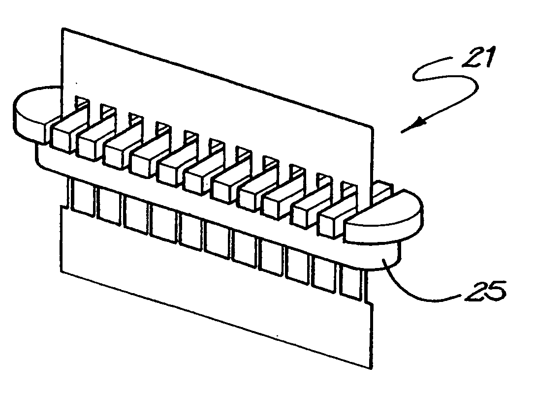
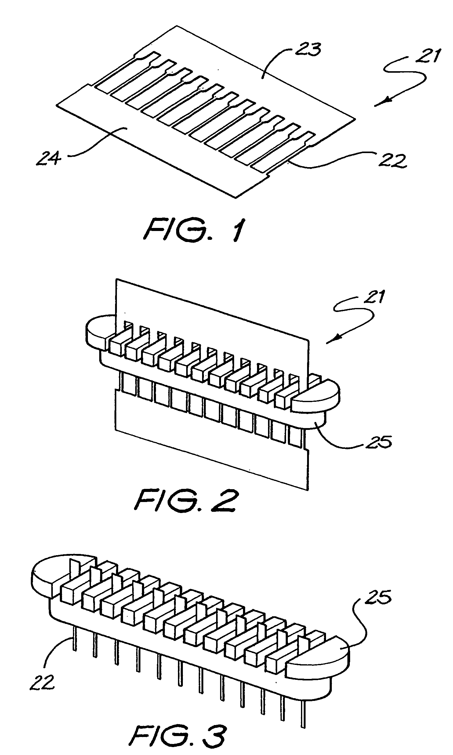
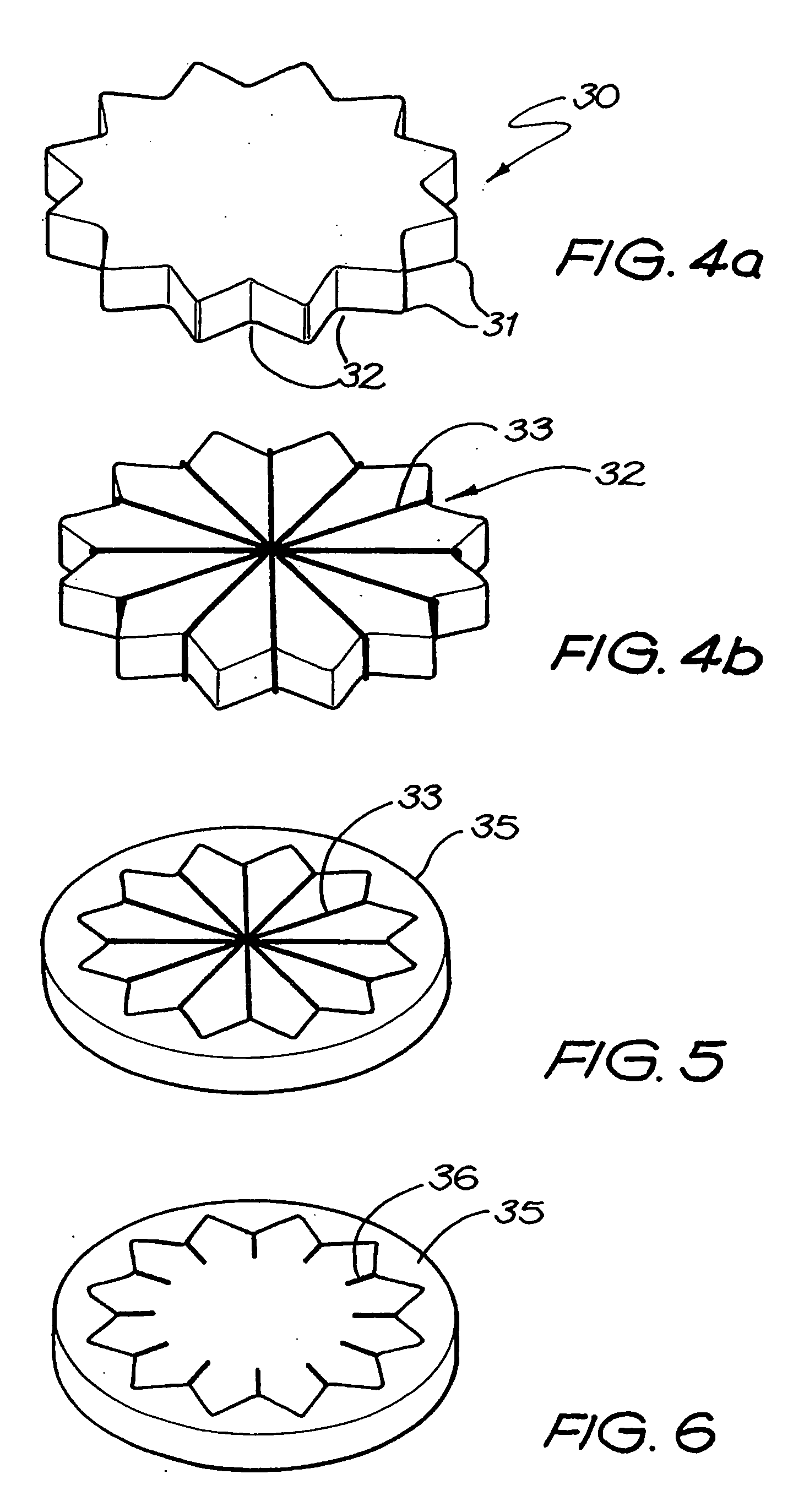
[0147] The method 10 comprises a first step 11 of forming an electrically conductive structure comprising a sacrificial component and non-sacrificial component. Different examples of such structures are depicted in FIGS. 1, 4b, 7, and 10b.

[0148] The method further comprises a step 12 of coating or moulding a non-electrically conductive insulative member on to at least a portion of the non-sacrificial component and not on to at least a portion of the sacrificial component of the conductive structure.

[0149] Still further, the method comprises a step 13 of then removing at least that portion of the sacrificial component of the conductive structure on to which the insulative member has not been coated or moulded.

[0150] Following removal of the sacrificial component of the conductive structure, the green body of the insulator can ...


PUM

PropertyMeasurementUnit
Lengthaaaaaaaaaa
Electrical conductivityaaaaaaaaaa
Shapeaaaaaaaaaa

Abstract

A method (10) of forming an electrically conducting feedthrough. The method (10) comprises a first step (11) of forming an electrically conductive structure (21) comprising a sacrificial component and a non-sacrificial component. At least a portion of the non-sacrificial component can then be coated with a relatively electrically insulating material (35) prior to removal of at least a portion of the sacrificial component from the electrically conductive structure. The structure of the feedthrough provides electrical connection through the wall of a housing of an implantable component while preventing unwanted transfer of materials between the interior of the component and the surrounding environment.

Description

FIELD OF THE INVENTION [0001] The present invention relates to a method of forming relatively small or miniature electrical connector systems. More specifically, the present invention relates to a method of forming hermetically sealed but electrically conducting feedthroughs for devices, including biosensors and implantable devices. Electrically conducting feedthroughs are also described. Examples of implantable devices that can use such feedthroughs include the implantable component of a cochlear implant hearing prosthesis. BACKGROUND OF THE INVENTION [0002] The term ‘feedthrough’ as used herein refers to the provision of an electrically conducting path extending through an insulative member, from one side of the insulative member to another. The electrically conducting path may extend from the interior of a hermetically sealed container or housing on one side of the insulative member, to an external location outside the container or housing on the other side of the insulative memb...

Claims


Application Information

Patent Timeline
IPC IPC(8): H01R13/40A61N1/05H01R13/52H01R43/00H01R43/24
CPCA61N1/05A61N1/0541H01R13/5224H01R43/24H01R2201/12Y10T29/4922Y10S439/909Y10T29/49117Y10T29/5149Y10T29/49204Y10T29/49002Y10T29/49174Y10T29/49073Y10T29/49169
Inventor DARLEY, DEREK IANMCCUSKER, DESMOND ANDREWMILOJEVIC, DUSANPARKER, JOHN
Owner COCHLEAR LIMITED
Why Eureka
Try Eureka