Supercharge Your Innovation With Domain-Expert AI Agents!

Hydraulic control apparatus

a control apparatus and hydraulic technology, applied in the direction of fluid couplings, gearings, servomotors, etc., can solve the problems of lowering operation efficiency, difficult layout of control equipment, and remarkable differences in flow rate or hydraulic pressur

Inactive Publication Date: 2006-06-29
TOSHIBA MASCH CO LTD
View PDF3 Cites 13 Cited by
  • Summary
  • Abstract
  • Description
  • Claims
  • Application Information

AI Technical Summary

Benefits of technology

The present invention provides a hydraulic control apparatus for a hydraulic shovel that includes a variable capacity pump, a first change over valve group, a delivery flow control means, a second change over valve group, an open and close motion valve, a compensation valve, and a bleed off passage. The hydraulic control apparatus allows for selective conduct of a bleed off function in case of operating relatively heavy load and in case of operating relatively light load. The technical effect of the invention is to improve the performance and efficiency of the hydraulic shovel by controlling the delivery flow rate of the variable capacity pump and optimizing the load sensing function of the change over valves.

Problems solved by technology

Accordingly, even when two or more actuators provided in the hydraulic shovel, each differing in inertia and load pressure very much, are operated simultaneously, the optimal operation for the property of each actuator can be performed, and in addition the problem of the cost up caused by arranging another pump for revolution operation and the problem that the layout of control equipments is difficult are solvable.
However, it has proved to be necessary for further improvement with regards to the hydraulic control circuit illustrated in FIG. 5, because the performance is largely affected by the load in case of driving an actuator with relatively heavy load of inertia like the revolution in the construction machinery such as the hydraulic shovel, which makes use of the above mentioned hydraulic control circuit, and because a hunting phenomenon occurs in the hydraulic circuit and the performance of the actuator becomes to be clumsy, particularly under the condition that small revolution orientation, that is, the boom is oriented nearly to the vertical direction, as the result, the moment of inertia becomes to be small, and the control input is fed back through the operator who manipulates the handling lever of the hydraulic shovel.
However, to discharge itself the pressurized hydraulic oil to the tank lowers the hydraulic pressure and flow rate in the hydraulic circuit, and as the result, induces lowering of operation efficiency.
But, in case that demand for the flow rate of pressurized oil increases because of complexity operation combining the heavy load caused by lifting heavy goods with the revolution operation, difference in the flow rate or in the hydraulic pressure becomes remarkable.
Furthermore, in case of forming a hydraulic oil passage between a spool of a valve body and inside of the valve body so as to enable to bleed off within the change over valve which controls the pressurized oil supply and discharge to and from a designated hydraulic actuator, this passage formed for bleeding off, as the result, conducts the bleed off, even when demand for the flow rate of pressurized oil increases because of complexity operation combining the heavy load with the revolution operation, and then the operation efficiency becomes worse.

Method used


Image

  • Hydraulic control apparatus
  • Hydraulic control apparatus
  • Hydraulic control apparatus

Examples


embodiment 1

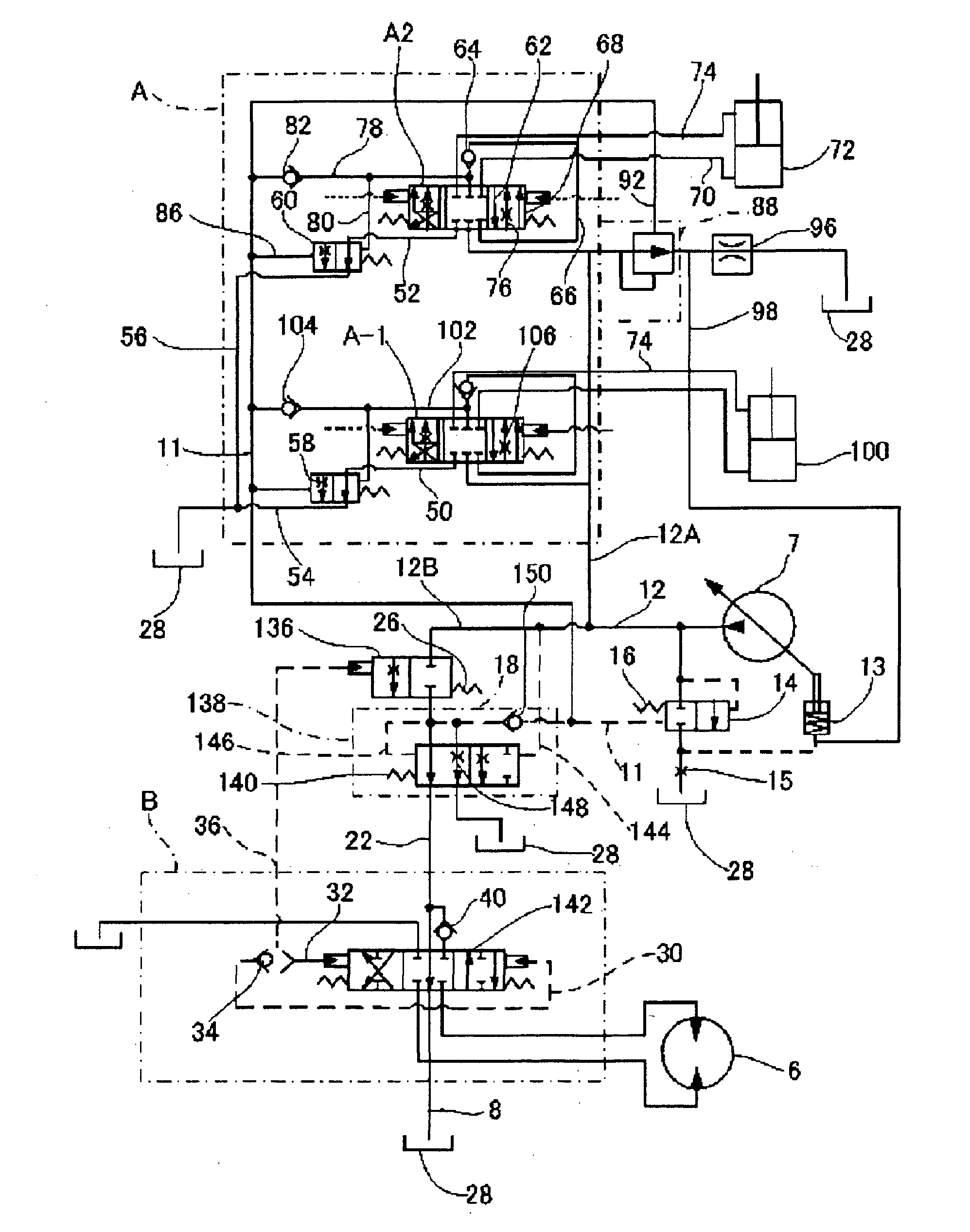
[0098] In FIG. 1, a reference numeral 7 designates a variable capacity pump. A delivery line 12 of the pump 7 branches delivery lines 12A and 12B. A first change over valve group A (hereinafter it is called a change over valve group A) is connected through the delivery line 12A to the variable capacity pump 7. A second change over valve group B (hereinafter it is called a change over valve group B) is connected through the delivery line 12B and a pressure compensation flow control means including an open and close motion valve 136 and a compensation valve 138 to the variable capacity pump 7.

[0099] A change over valve A-1 and a change over valve A-2 in the change over valve group A are connected in parallel with the delivery line 12 through the delivery line 12A, respectively.

[0100] There are provided with split flow compensation valve 58 and 60 between the return line 50 and 52 of the change over valves A-1 and A-2 and tank lines 54 and 56. The discharge hydraulic oil from the tan...

embodiment 2

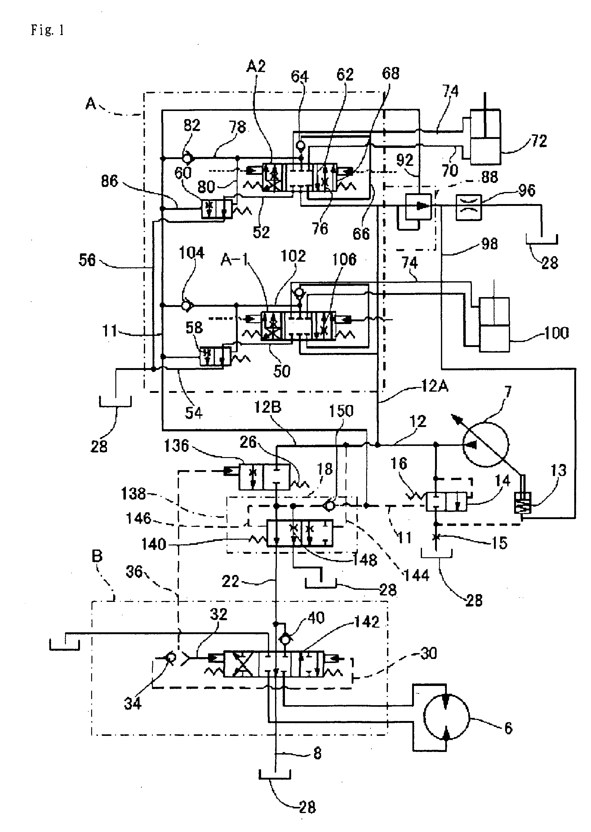
[0117]FIG. 2 illustrates the function of the open and close motion valve 136 shown in FIG. 1 being incorporated inside the directional change over valve 5 for the hydraulic motor 6 for revolution operation. In addition, as to the constitutional elements corresponding to those in the hydraulic circuit shown in FIG. 1, the same reference number is used in FIG. 2.

[0118] Accordingly, new constitutional portions will be mainly explained below.

[0119] In FIG. 2 reference numeral 2 is a compensation valve corresponding to the compensation valve 136 shown in FIG. 1.

[0120] A spool 2a (refer to FIG. 3 and FIG. 4) of the compensation valve 2 is forced in the direction of opening by a spring 3, and a hydraulic pressure room 10 of the compensation valve 2 is connected with the upstream of a variable throttle 1 in the directional change over valve 5, that is, the delivery line 12B, and a hydraulic pressure room 9 of the compensation valve 2 is connected with the downstream of the variable throt...

embodiment 3

[0125]FIG. 3 and FIG. 4 illustrate inside the each valve body of the directional change over valve 5 and the compensation valve 2, which are formed in one body in the hydraulic circuit configuration shown in FIG. 2.

[0126] In the condition of the neutral position of the directional change over valve 5, a spool 5a (refer to FIG. 3 and FIG. 4) of the directional change over valve 5, a port 134 (refer to FIG. 3 and FIG. 4) is connected with the tank 28 through the tank line 8.

[0127] On the other hand, the spool 5a connected through the passage 17A with the downstream of the compensation valve 2.

[0128]FIG. 3 illustrates whole of the cross sectional view taken along the axis direction of the hydraulic control apparatus according to the present invention in case of the sole revolution operation, and FIG. 4 illustrates whole of the cross sectional view taken along the axis direction of the hydraulic control apparatus according to the present invention in case of the complexity operation ...


PUM


Abstract

To provide a hydraulic control apparatus enabling to prevent failure due to occurrence of hunting, to elevate performance of a hydraulic control valve, and to improve operation efficiency through effectively conducting the bleed off. The hydraulic control apparatus is provided with a variable capacity pump 7, a first change over valve group A including at least one change over valve connected with a first delivery line 12A branched from a delivery line 12 of the variable capacity pump and arranged to have load sensing function, a second change over valve group B including at least one change over valve connected with a second delivery line 12B branched from the delivery line of the variable capacity pump, and an open and close motion valve 136 and a compensation valve 138 connected to the downstream of the open and close motion valve, which constitute a pressure compensation flow control means connected through the second delivery line and the second change over valve group. A hydraulic passage 148A is formed for bleeding off in the compensation valve, wherein the bleeding off is selectively conducted in accordance with a state of operation in the hydraulic circuit, in a way that in case of relatively small demand for the flow rate in the hydraulic circuit, such as the sole operation for revolution, the bleeding off is conducted so as to suppress the hunting, and in case that demand for the flow rate increases in the hydraulic circuit because of complexity operation combining the heavy load with the revolution operation, the bleeding off is not conducted.

Description

BACKGROUND OF THE INVENTION [0001] 1. Field of the Invention [0002] The present invention relates to a hydraulic control apparatus such as a construction machine, for example, a hydraulic shovel and etc., provided with a plurality of hydraulic actuators, and more specifically relates to the hydraulic control apparatus enabling to selectively conduct a bleed off function in a way that in case of operating relatively heavy load, a plurality of actuators are simultaneously operated and in case of operating relatively light load, only one actuator is operated at the same time, wherein in the case of the light load, failure due to occurrence of hunting is prevented by conducting the bleed off function, and in the case of the heavy load, performance of a hydraulic control valve is elevated by suppressing the bleed off function, thereby improving the operation efficiency as a whole. [0003] 2. Description of Related Art [0004]FIG. 5 illustrates a conventional hydraulic control circuit diagr...

Claims


Application Information

Patent Timeline
Patent Type & Authority Applications(United States)
IPC IPC(8): F16H31/00
CPCF15B11/055F15B2211/20546F15B2211/251F15B2211/30535F15B2211/329F15B2211/6052F15B2211/7053F15B2211/7058F16H59/26F16H61/40F16H61/4017F16H61/4061F16H61/4148F16H2059/6861E02F9/2207E02F9/2225F15B11/166F15B11/20
Inventor KOBAYASHI, MASAYUKIAOKI, KAZUMICHI
Owner TOSHIBA MASCH CO LTD
Features
  • R&D
  • Intellectual Property
  • Life Sciences
  • Materials
  • Tech Scout
  • Unparalleled Data Quality
  • Higher Quality Content
  • 60% Fewer Hallucinations
Learn More