Network usage analysis system using cost structure and revenue and method

a network usage analysis and cost structure technology, applied in the field of internet and wireless telephone networks, can solve the problems of increasing the potential for network congestion and bandwidth abuse by heavy users, increasing the usage difference between a heavy user and a light user, and limiting the bandwidth of most consumers today to the intern

Inactive Publication Date: 2006-06-29
JAGANNATHAN SRINIVASAN +2
View PDF19 Cites 12 Cited by
  • Summary
  • Abstract
  • Description
  • Claims
  • Application Information

AI Technical Summary

Problems solved by technology

Most consumers today have only limited access bandwidth to the Internet via an analog telephony modem, which has a practical data transfer rate upper limit of about 56 thousand bits per second.
As such, this higher access bandwidth significantly increases the potential for network congestion and bandwidth abuse by heavy users.
With this much higher bandwidth available, the usage difference between a heavy user and light user can be quite large.
These types of services increase the duration of time that a user is connected to the network as well as requiring significantly more bandwidth to be supplied by the service provider.

Method used


Image

  • Network usage analysis system using cost structure and revenue and method
  • Network usage analysis system using cost structure and revenue and method
  • Network usage analysis system using cost structure and revenue and method

Examples


Embodiment Construction

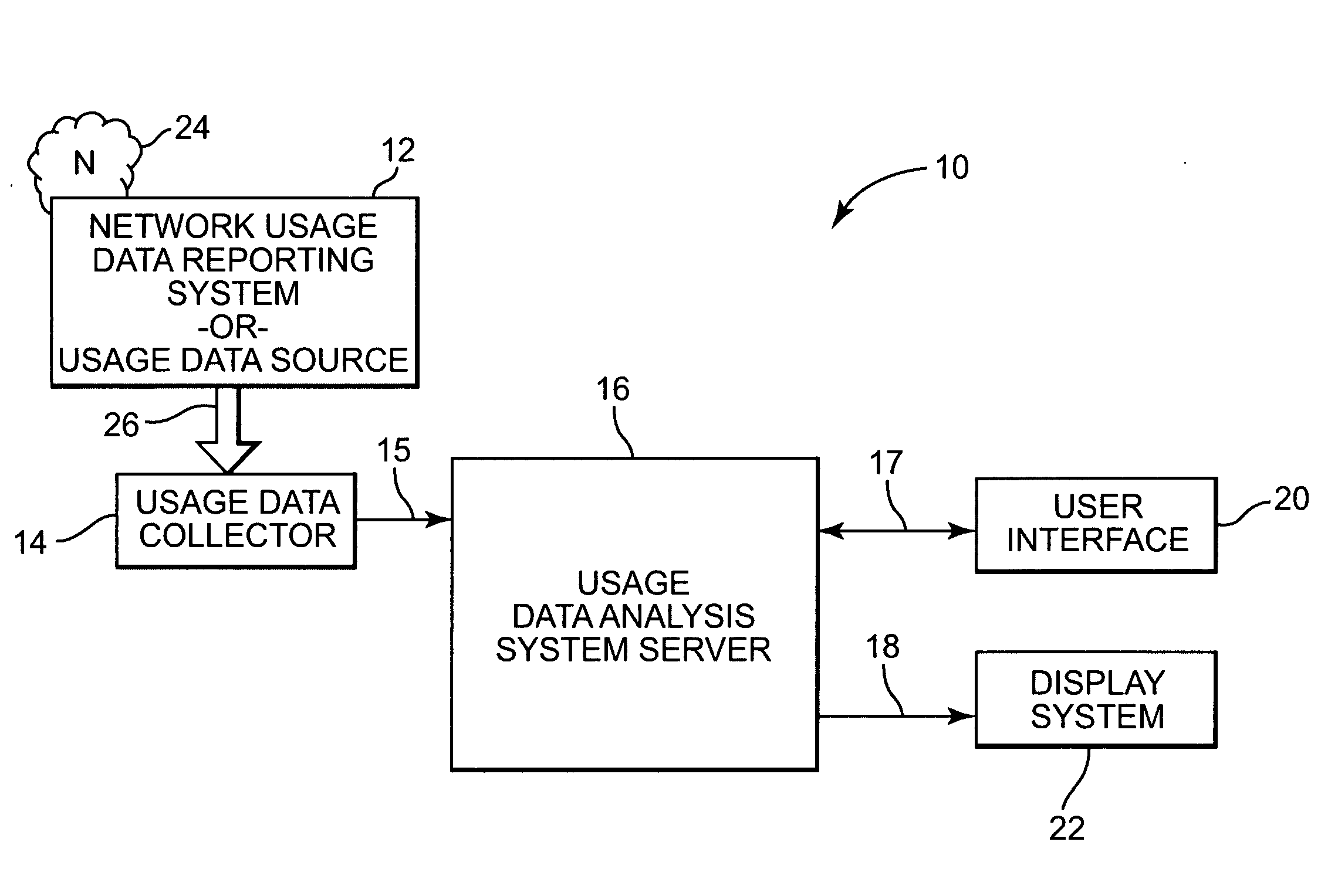
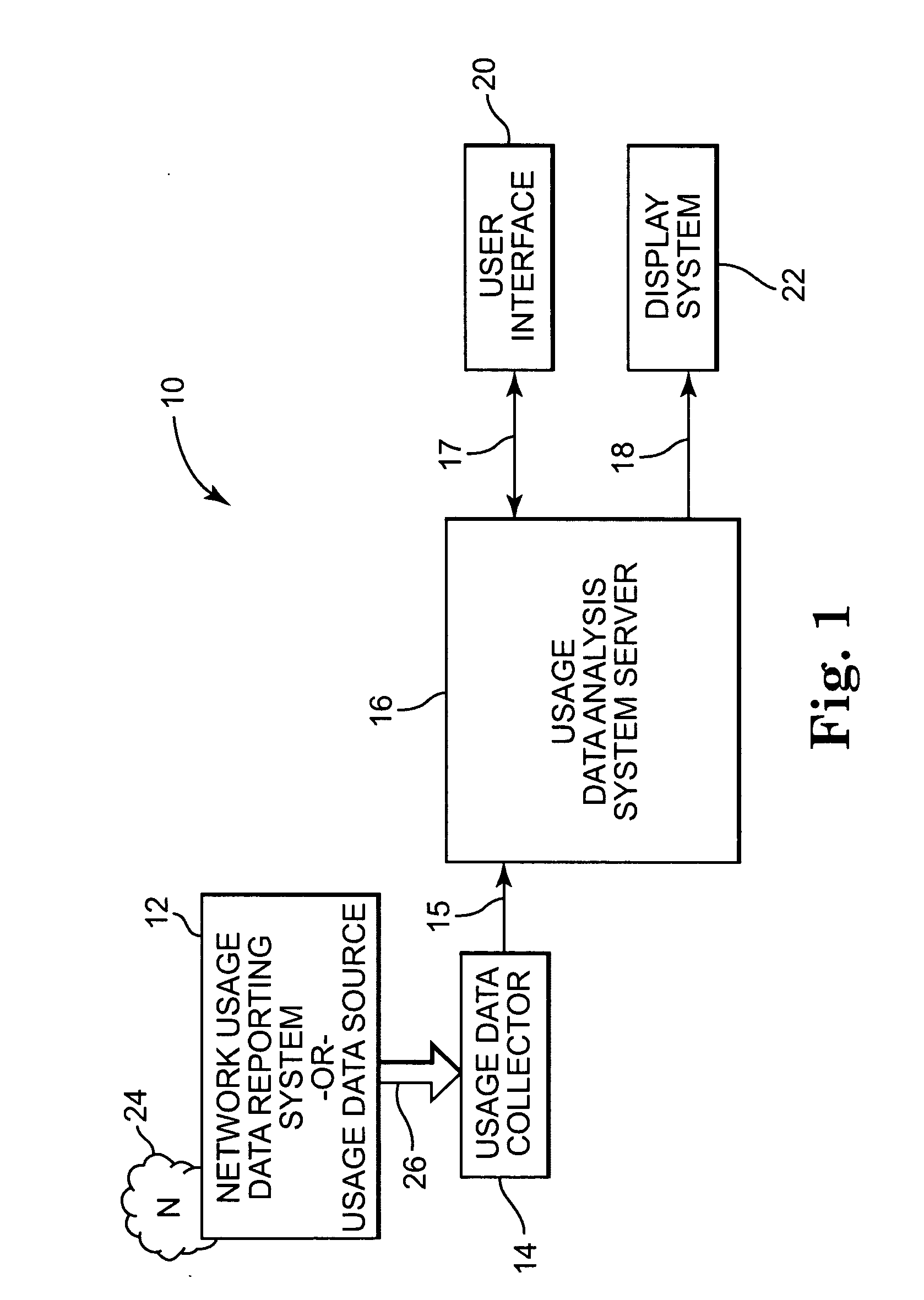
[0018] A network usage analysis system according to the present invention is illustrated generally at 10 in FIG. 1. Network usage analysis system 10 includes several main components, each of which comprises a software program. The main software program components of network usage analysis system 10 run on one or more computer or server systems. In one embodiment, each of the main software program components runs on its own computer system.

[0019] In one exemplary embodiment, network usage analysis system 10 includes a usage data collector 14, and a usage data analysis system server 16. Usage data collector 14 is coupled to usage data analysis system server 16 via communication link 15. Network usage analysis system 10 further includes user interface 20 and display system 22. User interface 20 and display system 22 are coupled to usage data analysis system server 16 via communication links 17 and 18, respectively.

[0020] Usage data collector 14 collects usage data 26. In one embodime...


PUM


Abstract

A network usage analysis system includes a data collector that is coupled to a network comprising a plurality of links over at least one selected geographic area. The data collector collects usage data corresponding to a level of use of the plurality of links, the cost of maintaining the plurality of links in the selected geographic area, and corresponding to the revenue generated from subscribers using the network in the selected geographic area. The system also includes a system server coupled to the data collector. The system server receives the usage data from the data collector and determines the economic feasibility for maintaining the network in the selected geographic area based on the subscriber usage data.

Description

CROSS-REFERENCE TO RELATED APPLICATIONS [0001] This application is related to the following concurrently filed U.S. patent application Ser. No.______, Docket No. 200205880-1; ______, Docket No. 200208404-1; ______, Docket No. 200208405-1; and ______, Docket No. 200208406-1, all of which are incorporated herein by reference.BACKGROUND OF THE INVENTION [0002] Network systems are utilized as communication links for everyday personal and business purposes. With the growth of network systems, particularly the Internet and wireless telephone networks, and the advancement of computer hardware and software technology, network use ranges from simple communication exchanges such as electronic mail to more complex and data intensive communication sessions such as web browsing, electronic commerce, and numerous other electronic network services such as Internet voice, and Internet video-on-demand. [0003] Network usage information does not include the actual information exchanged in a communicat...

Claims


Application Information

Patent Timeline
Patent Type & Authority Applications(United States)
IPC IPC(8): G06Q99/00
CPCG06Q30/00H04L43/062G06Q40/12
Inventor JAGANNATHAN, SRINIVASANALTMANN, JORNRHODES, LEE
Owner JAGANNATHAN SRINIVASAN
Why Eureka
Try Eureka