Apparatus and method for compensating a coriolis meter

a coriolis meter and apparatus technology, applied in the direction of volume metering, instruments, specific gravity measurement, etc., can solve the problems of increasing the amount of damping in the system, affecting and presenting operability challenges. achieve the effect of improving the accuracy of density and/or mass flow rate measuremen

Active Publication Date: 2006-12-26
EXPRO METERS
View PDF108 Cites 81 Cited by
  • Summary
  • Abstract
  • Description
  • Claims
  • Application Information

AI Technical Summary

Benefits of technology

[0008]Objects of the present invention include an apparatus having a device for determining the speed of sound propagating within a fluid flow in a pipe to determine the gas volume fraction of a process fluid or flow flowing within a pipe, and augment to improve the accuracy of a density and / or mass flow rate measurement of a coriolis meter.

Problems solved by technology

However, despite their success, Coriolis meters have been plagued by poor performance in two-phase flows, predominately bubbly flows of gas / liquid mixtures.
Coriolis meters have two fundamental issues with aerated or bubbly flows.
Firstly, bubbly flows present an operability challenge to coriolis meters.
Single phase mixtures introduce little damping to the vibration of the bent tubes, however, the amount of damping in the system dramatically increases with the introduction of gas bubbles.
As a result, more power is required to maintain vibration in the tubes in bubbly flows.
Often more power is required than is available, resulting in the “stalling” of the Corilois meter.
Futhermore, coriolis meters often require significant time to adjust for the often rapid changes in flow tube resonant frequencies associated with the onset of bubbly or aerated flows.
These time-delays, for which the flow tube is essentially stalled, greatly diminish the utility of coriolis meter in many applications where two phase flow and transient response are important such as batch processed.
Secondly, multiphase flows present an accuracy challenge.
The accuracy challenge presented by aerated flow regimes is that many of the fundamental assumptions associated with the principle of operation of Corilois meters become increasingly less accurate with the introduction of aerated flow.

Method used


Image

  • Apparatus and method for compensating a coriolis meter
  • Apparatus and method for compensating a coriolis meter
  • Apparatus and method for compensating a coriolis meter

Examples


Embodiment Construction

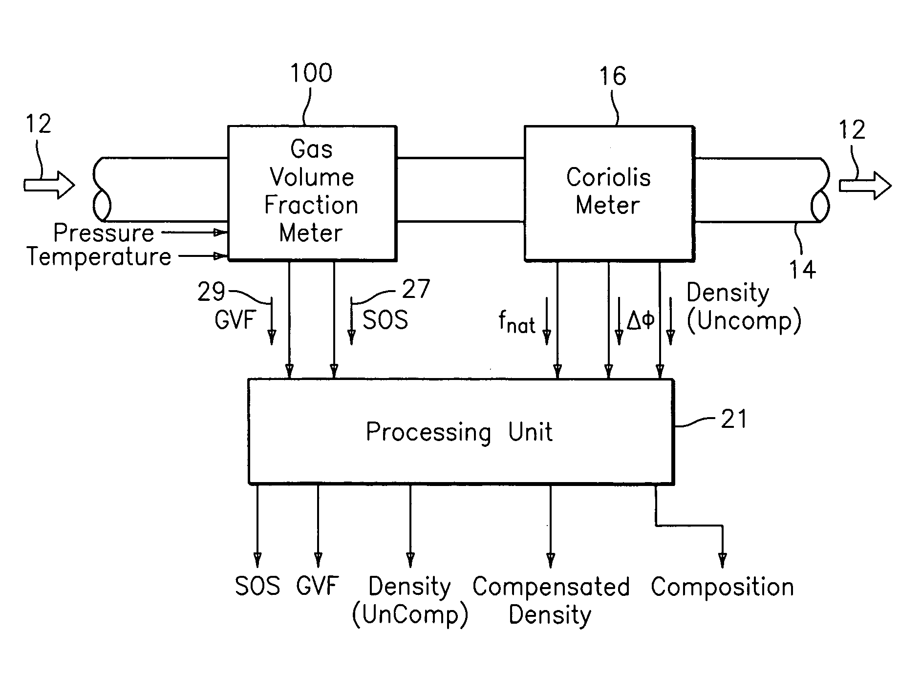
[0036]Coriolis meters provide a measurement of the mass flow and / or density of a fluid flow 12 passing through a pipe 14. As described in detail hereinbefore, a coriolis meter provides erroneous mass flow and density measurements in the presence of entrained gas within the fluid flow (e.g., bubbly gas). The present invention provides a means for compensating the coriolis meter to provide corrected or improved density and / or mass flow measurements.

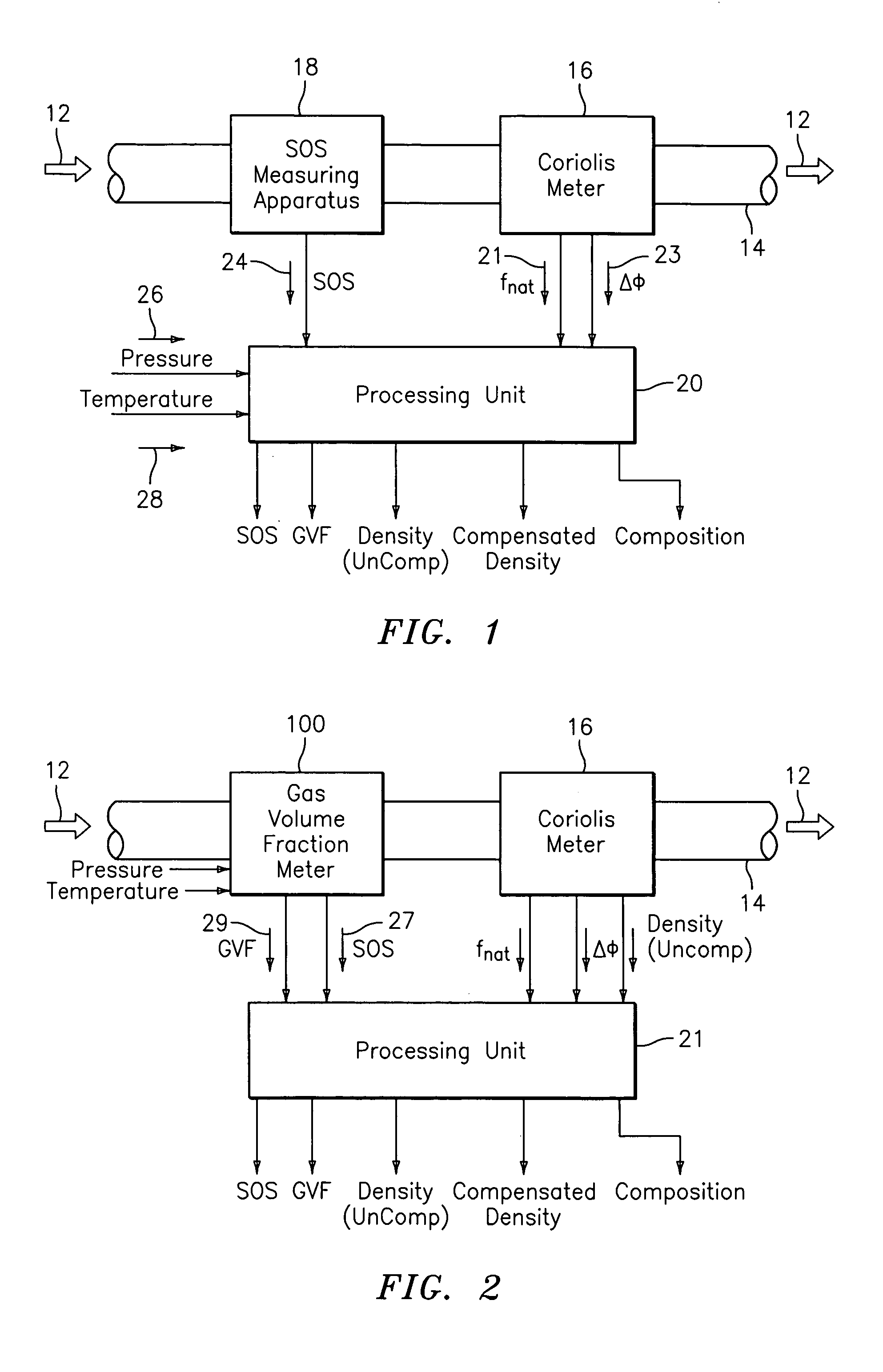
[0037]As shown in FIG. 1, one embodiment of a flow measuring system 10 embodying the present invention includes a coriolis meter 16, a speed of sound (SOS) measuring apparatus 18 and a processing unit 20 to provide any one or more of the following parameters of the fluid flow, namely, gas volume fraction, speed of sound propagating through the fluid flow, uncompensated density, compensated density and composition. The fluid flow may be any aerated fluid or mixture including liquid, slurries, solid / liquid mixture, liquid / liquid mixture and a...


PUM

PropertyMeasurementUnit
resonant frequencyaaaaaaaaaa
diameteraaaaaaaaaa
resonant frequencyaaaaaaaaaa

Abstract

A flow measuring system is provided that provides at least one of a compensated mass flow rate measurement and a compensated density measurement. The flow measuring system includes a gas volume fraction meter in combination with a coriolis meter. The GVF meter measures acoustic pressures propagating through the fluids to measure the speed of sound αmix propagating through the fluid to calculate at least gas volume fraction of the fluid and / or the reduced natural frequency. For determining an improved density for the coriolis meter, the calculated gas volume fraction and / or reduced frequency is provided to a processing unit. The improved density is determined using analytically derived or empirically derived density calibration models (or formulas derived therefore), which is a function of the measured natural frequency and at least one of the determined GVF, reduced frequency and speed of sound, or any combination thereof. The gas volume fraction (GVF) meter may include a sensing device having a plurality of strain-based or pressure sensors spaced axially along the pipe for measuring the acoustic pressures propagating through the flow.

Description

CROSS-REFERENCE TO RELATED PATENT APPLICATIONS[0001]The present invention claims the benefit of U.S. Provisional Patent Application No. 60 / 579,448 filed Jun. 14, 2004, U.S. Provisional Patent Application No. 60 / 570,321 filed May 12, 2004, U.S. Provisional Patent Application No. 60 / 539,640 filed Jan. 28, 2004, U.S. Provisional Patent Application No. 60 / 524,964 filed Nov. 25, 2003, U.S. Provisional Patent Application No. 60 / 512,794 filed Oct. 20, 2003, U.S. Provisional Patent Application No. 60 / 510,302 filed Oct. 10, 2003, U.S. Provisional Patent Application No. 60 / 504,785 filed Sep. 22, 2003, U.S. Provisional Patent Application No. 60 / 503,334 filed Sep. 16, 2003, U.S. Provisional Patent Application No. 60 / 491,860 filed Aug. 1, 2003, U.S. Provisional Patent Application No. 60 / 487,832 filed Jul. 15, 2003, which are all incorporated herein by reference.TECHNICAL FIELD[0002]This invention relates to an apparatus for measuring the density and / or mass flow rate of a flow having entrained g...

Claims


Application Information

Patent Timeline
Patent Type & Authority Patents(United States)
IPC IPC(8): G01N7/00G01F1/20G01N22/00G01F1/74G01F1/84G01N9/00
CPCG01F1/74G01F1/8413G01F1/8477G01F15/024G01F25/0007G01N9/002G01N2291/02818G01F25/10
Inventor GYSLING, DANIEL L.CURRY, PATRICKLOOSE, DOUGLAS H.BANACH, THOMAS E.
Owner EXPRO METERS
Why Eureka
Try Eureka