Power tool with a tool storage

a tool storage and power tool technology, applied in the field of power tools, can solve the problems of inconvenient replacement of tools and tool accessories, limited space capacity, and inability to replace tools, so as to facilitate the user to replace tools, prevent tools from being vibrated, and facilitate access

Inactive Publication Date: 2006-07-06
NANJING CHERVON IND
View PDF7 Cites 12 Cited by
  • Summary
  • Abstract
  • Description
  • Claims
  • Application Information

AI Technical Summary

Benefits of technology

[0011] Another object of the present invention is to provide a power tool with a tool storage compartment. The tool storage compartment contains a fastening means for fixing the tools within the compartment, and consequently to prevent the tools from being vibrated when the power tool is being operated. A still further object of the present invention is to conveniently allow access to the tools from the tool storage compartment.
[0012] Provided with such mechanisms, the power tool is equipped with a detachable tool storage compartment, which facilitates the user to replace the tools at any moment. Moreover, it is very convenient to access the tools and assemble or disassemble the tool storage compartment from the tool housing. Furthermore, because the tool storage compartment is equipped with means for securing it to the housing, it is less likely that vibrations caused during use of the power tool will move the tool storage compartment around or even slide out of the engagement with the housing.

Problems solved by technology

In addition, tools and tool accessories might need to be replaced when a saw blade or drill bit becomes too dull.
This is extremely inconvenient.
For receiving those tools, a relatively large space must be provided in the housing of the power tool, and the space capability is relatively limited.
Meanwhile, during operation of the power tool, tools and tool accessories are subjected to high levels of vibrations, which make securing the tools and / or accessories difficult.
Furthermore, the tools are inconvenient in accessing because the tool storage has a relative small volume.

Method used


Image

  • Power tool with a tool storage
  • Power tool with a tool storage
  • Power tool with a tool storage

Examples


Embodiment Construction

[0020] While this invention is susceptible of embodiments in many different forms, there is shown in the drawings and will herein be described in detail preferred embodiments of the invention with the understanding that the present disclosure is to be considered as an exemplification of the principles of the invention and is not intended to limit the broad aspect of the invention to the embodiments illustrated.

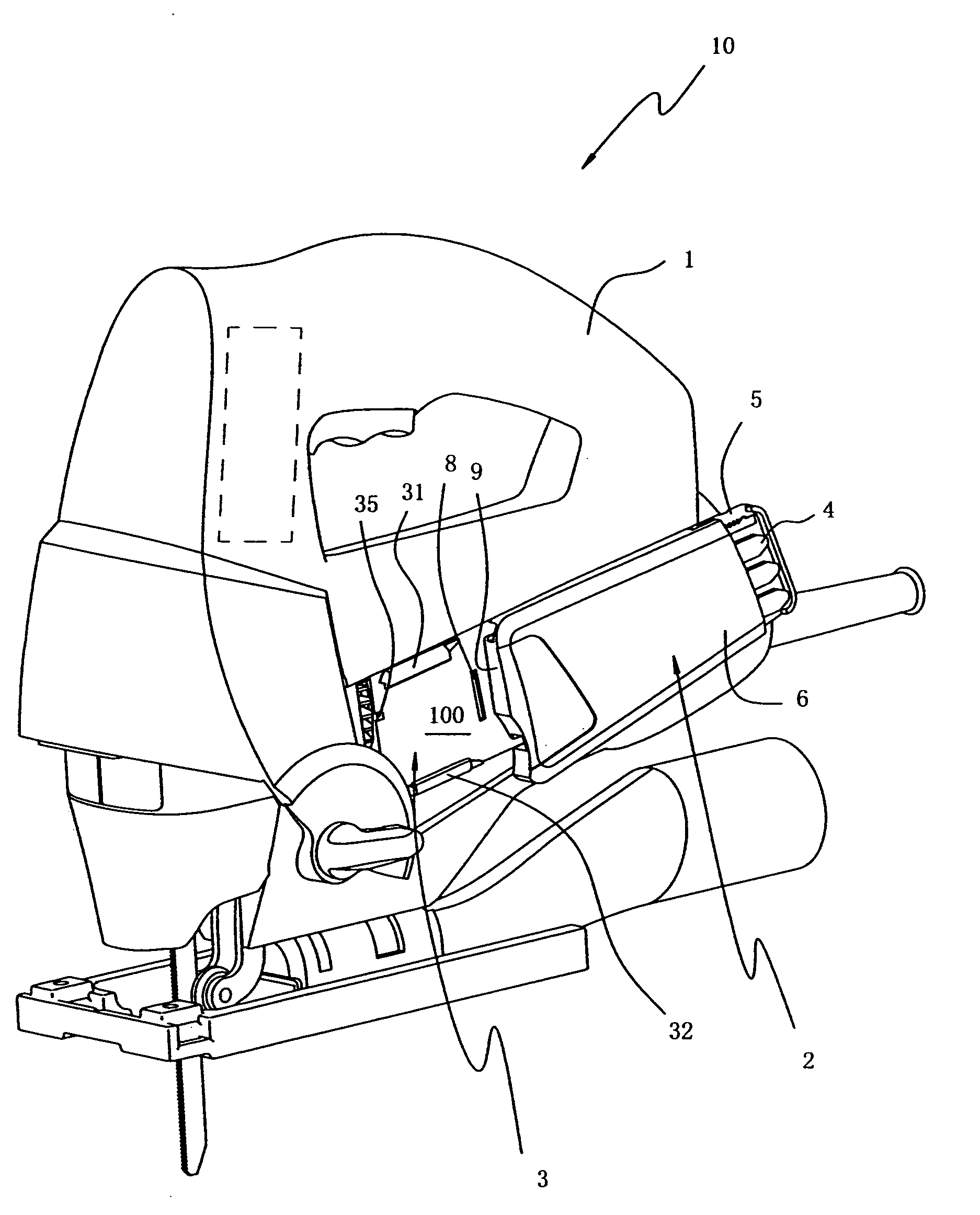
[0021] Referring to FIG. 1, a jig saw 10 includes a housing 1, a locking device 3 on the outer surface of the housing 1 for detachably connecting a blade storage compartment 2. The locking device 3 is not limited to the position shown in the drawings, other proper positions on the housing, such as the position shown in dashed lines of FIG. 1 are also contemplated by the present invention.

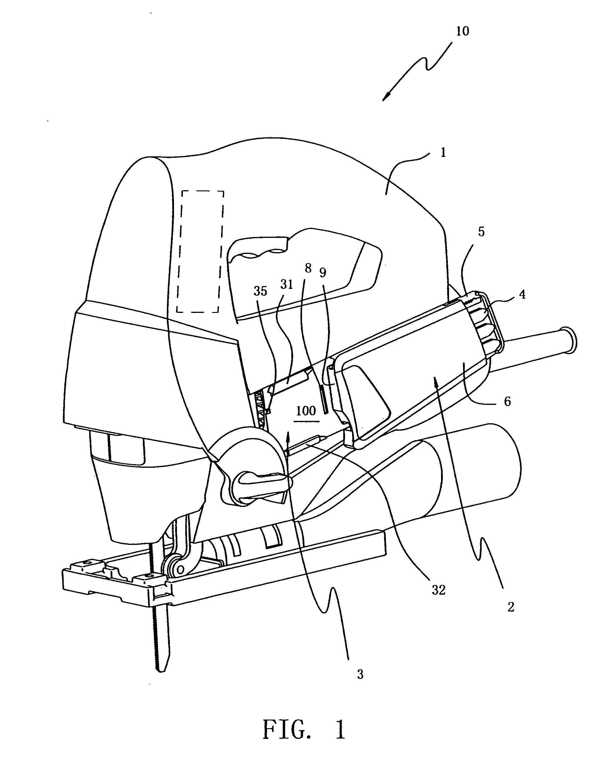
[0022] Further referring to FIGS. 2 and 3, the locking device 3 includes guide bars 31, 32, 33, and 34, which are arranged to be engagable with sliding slots 25, 26 of the tool storage compa...


PUM

PropertyMeasurementUnit
resilientaaaaaaaaaa
forceaaaaaaaaaa
shapesaaaaaaaaaa

Abstract

The present invention discloses a power tool with a tool storage compartment. The power tool includes a housing and a tool storage compartment detachably mounted onto the outside of the housing for storing spare tools and power tool accessories. The power tool housing contains at least one guide bar and a sliding slot is disposed on a surface of the tool storage compartment acting with the housing. The guide bar and the sliding slot are engageable with each other, such that the tool storage compartment is slidable relative to the housing. The tool storage compartment and the housing respectively comprise fixing means for engaging with each other. The tool storage compartment can be automatically locked when it slides along the guide bar and reaches a predetermined position. Additionally, the tool storage compartment further includes a mechanism for fastening the tools and a device for conveniently accessing the tools. Provided with such mechanisms, the power tool is equipped with a detachable tool storage compartment that allows the user to conveniently access the tools or tool accessories at any moment.

Description

CROSS-REFERENCE TO RELATED APPLICATIONS [0001] This application claims priority under 35 U.S.C. § 119 to Chinese Application No. 200520069605.2, filed on Jan. 4, 2005. FEDERALLY SPONSORED RESEARCH OR DEVELOPMENT [0002] None. TECHNICAL FIELD [0003] The invention relates to a power tool, and more particularly to a cutting tool with a tool storage, for storing types of tools and tool accessories which might be needed by the user during the use and operation of the power tool. BACKGROUND OF THE INVENTION [0004] Power tools, especially portable cutting tools, such as jig saws, circular saws and electric drills, are widely used in different locations and for different applications because of their portability. During operation, power tool accessories (e.g., saw blades, drill bits, etc.) are needed to be replaced to accommodate workpieces that have different material or shapes. In addition, tools and tool accessories might need to be replaced when a saw blade or drill bit becomes too dull....

Claims


Application Information

Patent Timeline
Patent Type & Authority Applications(United States)
IPC IPC(8): B26B11/00
CPCB23D51/03B25F5/029
Inventor WU, SHUMING
Owner NANJING CHERVON IND
Why Eureka
Try Eureka