Sawing machine, cutting-off method, and method of reducing noise

Inactive Publication Date: 2006-07-06
AMADA CO LTD
View PDF23 Cites 25 Cited by
  • Summary
  • Abstract
  • Description
  • Claims
  • Application Information

AI Technical Summary

Benefits of technology

[0035] According to the noise reduction method and the sawing machine in the fifteenth to the twenty-first aspects, by suddenly accelerating and decelerating the rotation speed of the band saw blade, the rotation speed of the band saw blade can be vibrated, thereby realizing a mode in w

Problems solved by technology

In the configuration in which the speed reducer is placed between the motor and the driving wheel, however, the number of components increases to make the configuration complicated, and maintenance is required relatively frequently.
Furthermore, there is a problem in that the moment of inertia increases to make it difficult to perform micro-control of the saw speed.
Conventionally, the saw speed is controlled during cutting of the workpiece by the band saw blade, however, it is to control the saw s

Method used


Image

  • Sawing machine, cutting-off method, and method of reducing noise
  • Sawing machine, cutting-off method, and method of reducing noise
  • Sawing machine, cutting-off method, and method of reducing noise

Examples


first embodiment

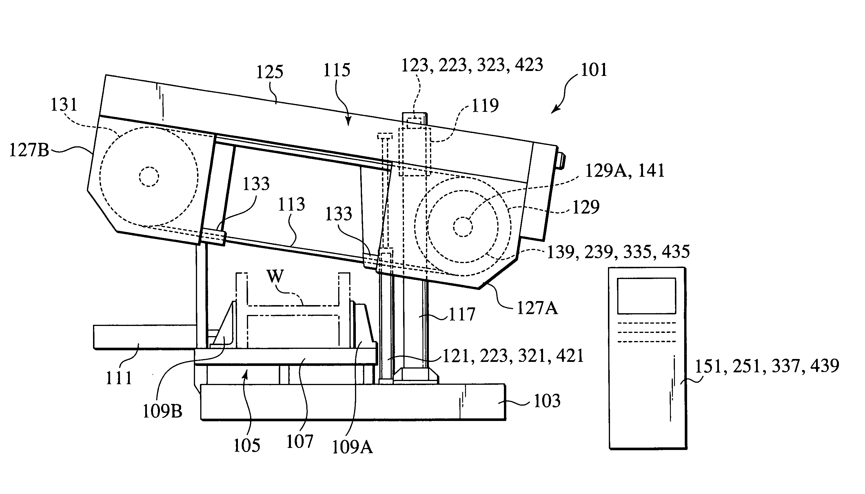
[0077] While the horizontal band saw machine is exemplified as the band saw machine in the above explanation, the first embodiment is also applicable to the vertical band saw machine.

second embodiment

[0078] the present invention will be explained next.

[0079] In the second embodiment, the control device 151 in the first embodiment of the present invention is partly modified. A control device 251 in the second embodiment includes, as shown in FIG. 7, a saw speed controller 259 instead of the rotation speed controller 159, and a vibration signal applying unit 263 instead of the rectangular pulse generator 163. Even the second embodiment can exhibit the same effect as in the first embodiment.

[0080] A third embodiment of the present invention will be explained. The third embodiment of the present invention relates to a cutting method of the workpiece by a sawing machine and the sawing machine. More specifically, the third embodiment relates to a cutting method and a sawing machine, in which when the noise, the wear, or the cutting resistance of the sawteeth reaches and exceeds a reference value at the time of cutting a workpiece, the rotation speed of the saw blade is vibrated to co...


PUM

PropertyMeasurementUnit
Frequencyaaaaaaaaaa
Lengthaaaaaaaaaa
Electrical resistanceaaaaaaaaaa

Abstract

A band saw machine includes a driving wheel and a driven wheel around which an endless band saw blade is wound. At least one of the driving wheel and the driven wheel is directly connected to an output shaft of a control motor. The output shaft of the control motor is arranged in a cylindrical bearing unit installed on a motor base supporting the control motor. The driving wheel is rotatably supported by the bearing unit.

Description

TECHNICAL FIELD [0001] The present invention relates to a sawing machine, a cutting method, and a noise reduction method. More particularly, the present invention relates to a sawing machine, in which a driving wheel around which a band saw blade is wound on a band saw machine and an output shaft of a control motor such as a servomotor are directly connected with each other, and a cutting method and a noise reduction method in the band saw machine. BACKGROUND ART [0002] In the band saw machine in the background art, as shown in FIG. 1, a motor 34 for rotating a driving wheel 29 is fitted to the back of a wheel housing 27A, and a speed reducer 37 formed of, for example, a planetary gear mechanism or a worm gear mechanism is equipped between an output shaft 35 of the motor 34 and a shaft 29A of the driving wheel 29. This configuration is disclosed in Japanese Patent Application Laid-Open No. H11-104915. [0003] Conventionally, in order to cut a workpiece while keeping the cutting rate ...

Claims


Application Information

Patent Timeline
IPC IPC(8): B23D55/00B23D55/06
CPCB23D55/005B23D59/001B23D55/06Y10T83/04Y10T83/0605Y10T83/141Y10T83/148Y10T83/159Y10T83/707Y10T83/7076
Inventor TOKIWA, TORUNAITO, KINSHIRO
Owner AMADA CO LTD
Why Eureka
Try Eureka