Splittable hemostasis valve

a hemostasis valve and splitter technology, applied in the field of splittable hemostasis valves, can solve the problems of high manufacturing cost of prior art valves, difficult to split prior art valves, and complex mold geometry

Inactive Publication Date: 2006-07-06
PACESETTER INC
View PDF9 Cites 14 Cited by
  • Summary
  • Abstract
  • Description
  • Claims
  • Application Information

AI Technical Summary

Benefits of technology

[0019] The present invention, in one embodiment, is a splittable hemostasis valve for coupling to a splittable catheter or sheath. The valve includes a first valve wall, a second valve wall, a feature for maintaining the valve walls in an assembled condition, and a membrane. The first valve wall includes an end adapted to couple to the catheter or sheath. The end includes an integral sealing ring extending along an outer circumferential surface of said end. The second valve wall includes an end adapted to couple to the catheter or sheath. The end includes an integral sealing ring extending along an outer circumferential surface of said end. The membrane extends between the valve walls. The membrane, sealing rings and at least a portion of the valve walls are formed from the same resilient material.
[0020] In one embodiment, the feature for maintaining the valve walls in an assembled condition is a binder extending about an outer circumferential surface of the valve walls. In another embodiment, the feature for maintaining the valve walls in an assembled condition is a mechanically coupled joint.

Problems solved by technology

However, these prior art valves have two disadvantages.
First, the prior art valves can be overly difficult to split.
Second, the prior art valves typically involve complex mold geometry and / or bonding methods such as sonic welding.
Thus, the prior art valves are expensive to manufacture.

Method used


Image

  • Splittable hemostasis valve
  • Splittable hemostasis valve
  • Splittable hemostasis valve

Examples


Embodiment Construction

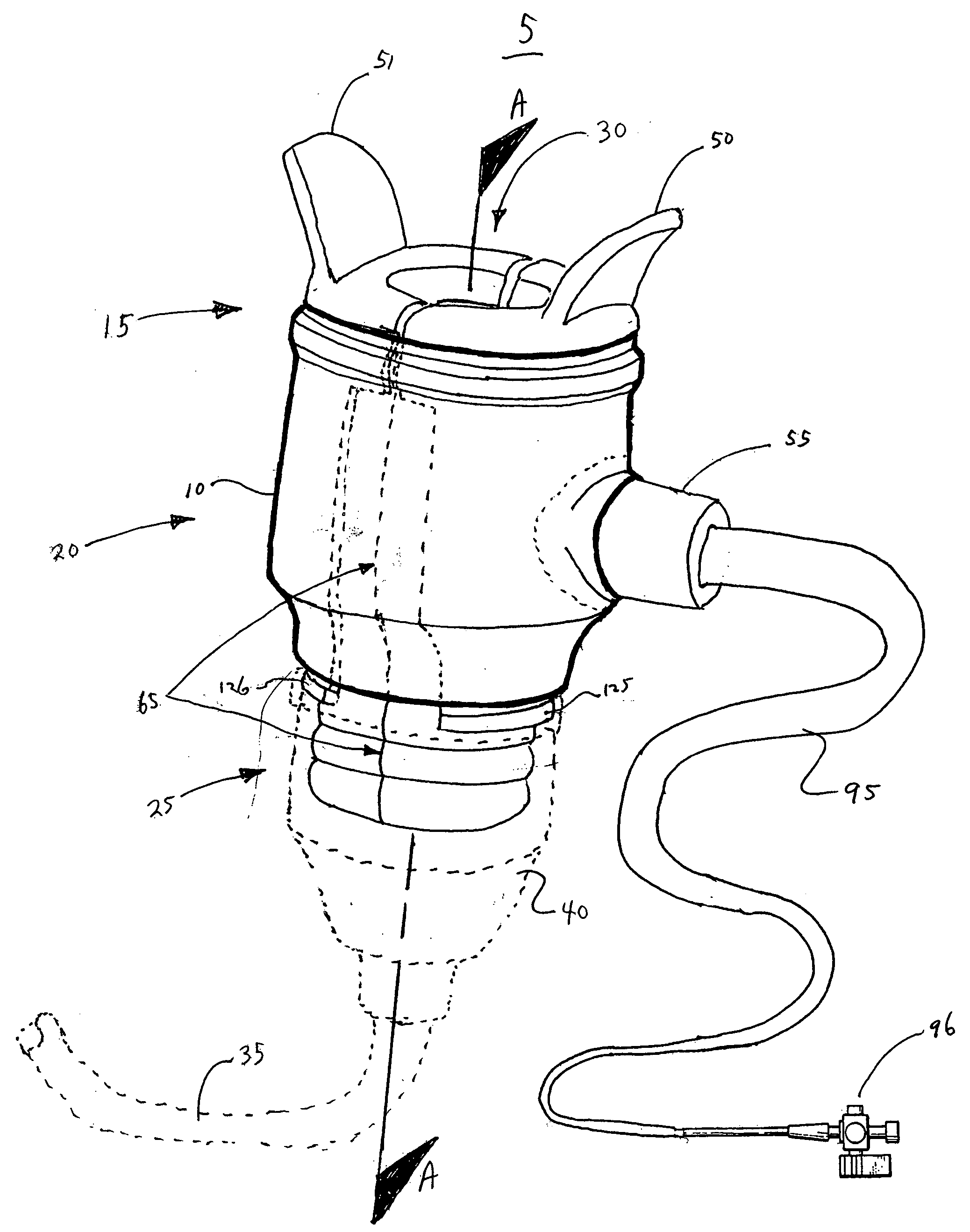
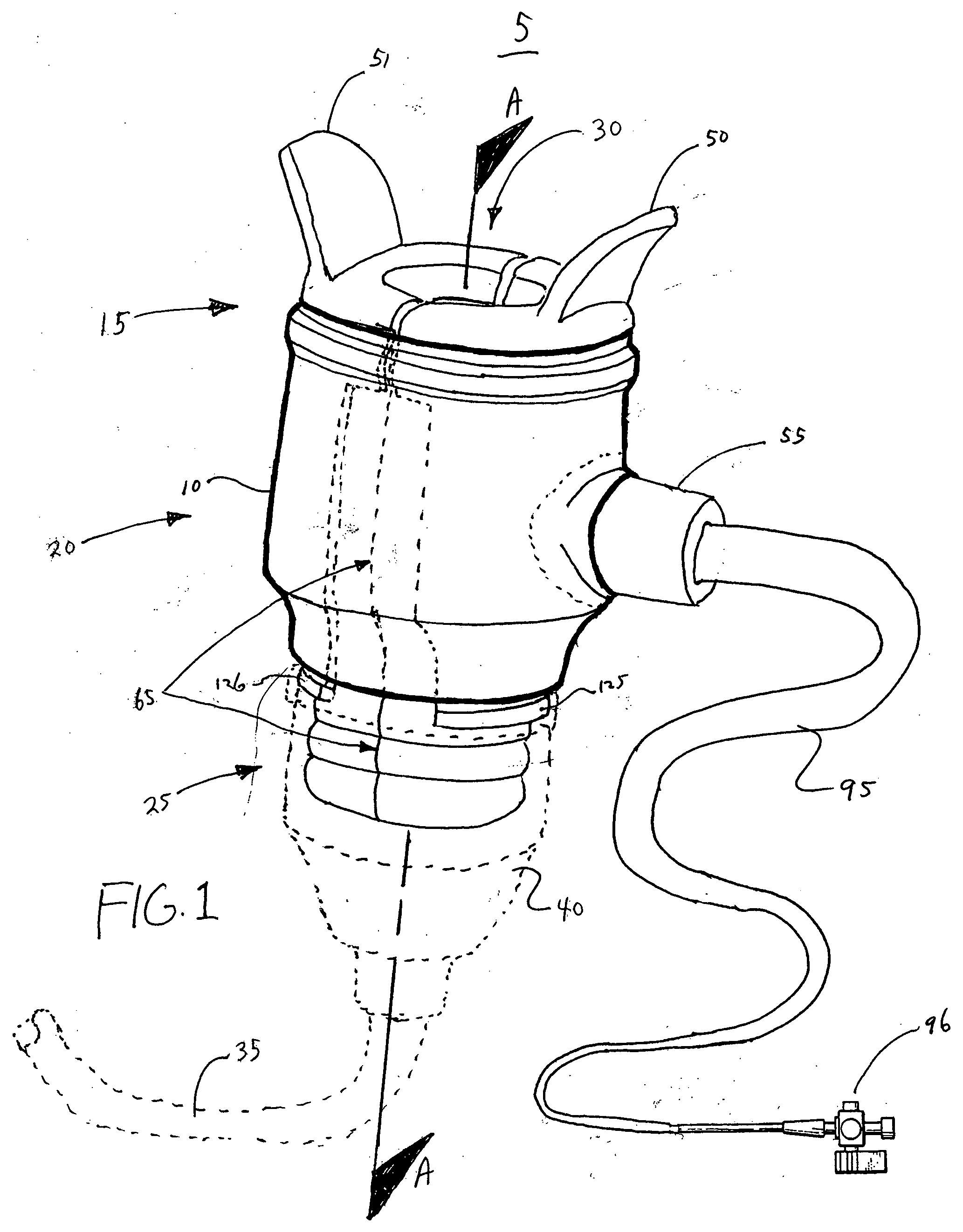
[0031]FIG. 1 is an isometric view of one embodiment of the present invention, which is a splittable multi-piece hemostasis valve 5 that is held together in an assembled condition via a sleeve 10 formed about the assembled valve 5. In one embodiment, the sleeve 10 is a thin polymer material shrink-wrapped about the valve 5. When the valve 5 needs to be split in order to clear a device (e.g., a pacemaker lead or other medical device), the sleeve 10 is split and the valve 5 is disassembled.

[0032] The valve 5 is advantageous for multiple reasons. First, because the valve 5 is assembled from multiple pieces and then shrink-wrapped together, it offers reduced manufacturing costs as compared to prior art splittable hemostasis valves. Second, the valve requires less effort to split than prior art splittable hemostasis valves.

[0033] As shown in FIG. 1, the valve 5 includes an entry end 15, a generally cylindrical body portion 20, and an attachment end 25. The entry end 15 has an opening 30...


PUM

PropertyMeasurementUnit
angleaaaaaaaaaa
flexibleaaaaaaaaaa
lengthsaaaaaaaaaa

Abstract

The present invention is a splittable multi-piece hemostasis valve that is held together in an assembled condition via a binder formed about the assembled valve. The binder may be a sleeve of thin polymer material shrink-wrapped about the valve. When the valve needs to be split in order to clear a medical device such as a pacemaker lead, the sleeve is split and the valve is disassembled.

Description

FIELD OF THE INVENTION [0001] The present invention relates to hemostasis valves and methods of making and using such valves. More particularly, the present invention relates to splittable hemostasis valves and methods of making and using such valves. BACKGROUND OF THE INVENTION [0002] Splittable hemostasis valves are known in the art. However, these prior art valves have two disadvantages. First, the prior art valves can be overly difficult to split. Second, the prior art valves typically involve complex mold geometry and / or bonding methods such as sonic welding. Thus, the prior art valves are expensive to manufacture. [0003] There is a need in the art for a splittable hemostasis valve that requires less effort to split and is less expensive to manufacture. There is also a need in the art for a method of manufacturing and a method of splitting such a valve. BRIEF SUMMARY OF THE INVENTION [0004] The present invention, in one embodiment, is a splittable hemostasis valve. The valve co...

Claims


Application Information

Patent Timeline
Patent Type & Authority Applications(United States)
IPC IPC(8): F16K1/00
CPCA61M39/0606A61M2039/062A61M2039/0633A61M2039/064A61M2039/0686F16K27/12
Inventor RICKERD, CLAUDEHONOUR, KIRKPOTTER, DANIEL J.
Owner PACESETTER INC
Why Eureka
Try Eureka