Surface acoustic wave device

a surface acoustic wave and waveguide technology, applied in piezoelectric/electrostrictive/magnetostrictive devices, piezoelectric/electrostriction/magnetostriction machines, electrical equipment, etc., can solve the problem of difficult to achieve broadband characteristics, sharp increase in frequency variation, etc. problem, to achieve the effect of easy setting of turnover temperature around room temperatur

Inactive Publication Date: 2006-07-06
SEIKO EPSON CORP
View PDF7 Cites 5 Cited by
  • Summary
  • Abstract
  • Description
  • Claims
  • Application Information

AI Technical Summary

Benefits of technology

[0018] Further, in the surface acoustic wave device, the multiplication H / λ·mr of the electrode thickness H / λ and metalization ratio mr is set in the range of 0.004≦H / λ·mr≦0.019, when the metalization ratio mr of the electrode fingers of the IDT is represented by (electrode finger widths) / (electrode finger widths+spaces between electrode fingers). Therefore, a second-order temperature coefficient can be made smaller than that in the related art, and the turnover temperature can be easily set around room temperature.
[0019] Furthermore, according to the second aspect, the surface acoustic wave device is used for a complex device such as an oscillation circuit and a module device. Therefore, a module device or an oscillation with high-performance can be provided.

Problems solved by technology

Therefore, if the available temperature range is expanded, a problem occurs in which the amount of frequency variation sharply increases.
In addition, since the electromechanical coupling coefficient k2 of the ST cut quartz SAW device is small, it is difficult to achieve characteristics of a broadband when a filter is provided.
On the other hand, a second-order temperature coefficient of the frequency temperature characteristic is substantially equal to that of the ST cut quartz SAW device, and the problem still remains in which the amount of frequency variation sharply increases when the available temperature range is expanded.

Method used


Image

  • Surface acoustic wave device
  • Surface acoustic wave device
  • Surface acoustic wave device

Examples


Embodiment Construction

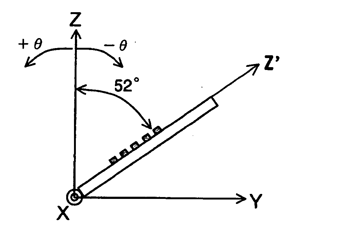
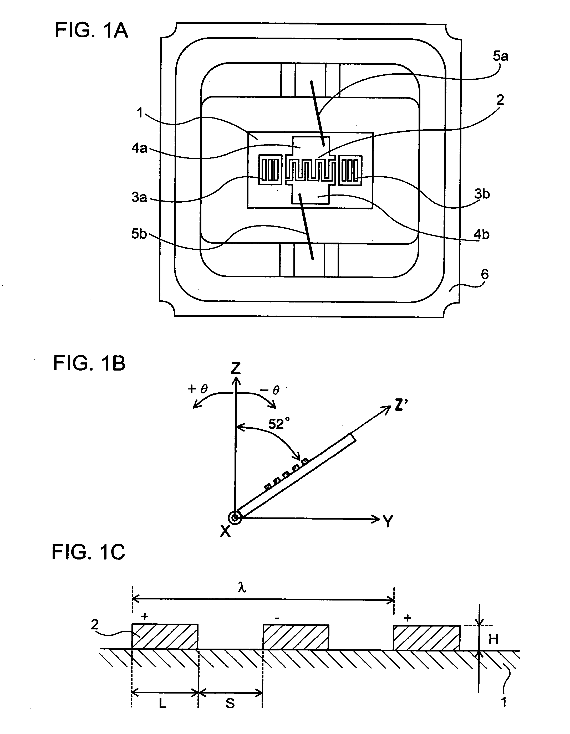
[0027] Hereinafter, a preferred embodiment of the invention will be described in detail with reference to the accompanying drawings. FIG. 1A is a plan view of an SAW resonator according to the invention. The SAW resonator has a structure in which an IDT 2, constructed with positive electrode fingers and nagative electrode fingers that are alternately inserted therein, and grating reflectors 3a and 3b for reflecting a surface acoustic wave by both sides of the IDT 2, on a piezoelectric substrate 1. Input / output pads 4a and 4b of the IDT 2 are electrically connected to input / output terminals of a package 6 by metal wires 5a and 5b, and an opening of the package 6 is air-tightly sealed by a lid. As shown in FIG. 1B, the piezoelectric substrate 1 is a quartz plate in which a cut angle θ of a rotated Y-cut quartz substrate is set to a position that is rotated in counter-clockwise direction by −52° from a crystal Z-axis, and in which a propagation direction of the SAW is set in a Z′-axis ...


PUM


Abstract

A surface acoustic wave device has a piezoelectric substrate and an IDT formed on the piezoelectric substrate, and uses an excited wave as an SH wave. The piezoelectric substrate is a quartz plate in which a cut angle θ of a rotated Y-cut quartz substrate is set in the range of −65°≦θ≦−51° in a counter-clockwise direction from a crystal Z-axis and the propagation direction of a surface acoustic wave is set in the range (90°±5°) with respect to a crystal X-axis. The IDT is made of Ta or an alloyed metal containing Ta as the main component.

Description

BACKGROUND [0001] 1. Technical Field [0002] The present invention relates to a surface acoustic wave device using a quartz substrate and, in particular, to a surface acoustic wave device which can achieve excellent frequency temperature characteristic of a broadband. [0003] 2. Related Art [0004] In recent years, a surface acoustic wave (hereinafter, referred to as SAW) device has been widely used in mobile communication terminal or other apparatuses for a vehicle. In particular, a surface acoustic wave device is required to have excellent frequency temperature characteristic of a broadband. [0005] An SAW device, using an ST cut quartz substrate as an SAW device according to the related art, has been proposed. The ST cut quartz substrate is a cut name of a quartz substrate having a plane (XZ′ plane) which is rotated in the counter-clockwise direction from an XZ plane about a crystal X-axis by 42.75° from a crystal Z-axis, and uses an SAW (hereinafter, referred to as “ST cut quartz SA...

Claims


Application Information

Patent Timeline
Patent Type & Authority Applications(United States)
IPC IPC(8): H03H9/25
CPCH03H9/02551H03H9/02834H03H9/14538
Inventor MORITA, TAKAOOWAKI, TAKUYA
Owner SEIKO EPSON CORP
Why Eureka
Try Eureka