
Automatic component testing

Inactive Publication Date: 2006-07-06
STEINBICHLER OPTOTECHN
View PDF13 Cites 96 Cited by
  • Summary
  • Abstract
  • Description
  • Claims
  • Application Information

AI Technical Summary

Benefits of technology

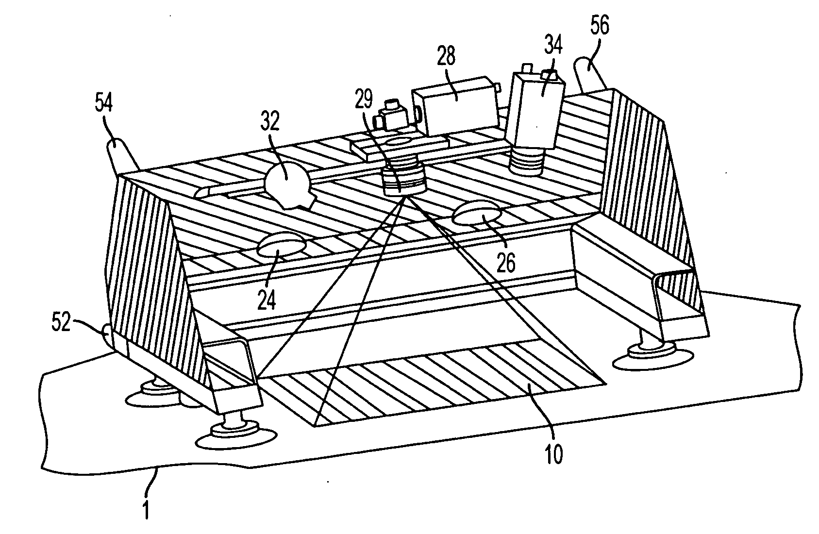
[0036] The apparatus for the testing of a component advantageously includes a digitizing system for the determination of the 3D contour data of the component. This embodiment makes it possible to sense the 3D contour data of the component simultaneously with the testing of the component. This is in particular advantageous when the 3D contour data are not otherwise available. It is furthermore advantageous for the digitizing system to be integrated into the sensor unit. The apparatus in accordance with the present disclosure can thereby be made particularly compact so that they only consist of two main elements, namely the base unit of the tracking system and the sensor unit. This simplifies the operation.
[0037] In a further embodiment, a strip projection sensor is used as the digitizing system which includes a strip projector, a camera and a corresponding measured data processing system. It is particularly ad

Problems solved by technology

A disadvantage of the already known test methods consists of the fact that only one single section of the component can be tested in a specific position of the test sensor, i.e. in an individual measurement.
In this process, it is difficult to work through the test plan without markings on the component.
A precise positioning of the test sensor is furthermore only possible with difficulty since the sensor has to be positioned by hand.
Furthermore, there is the problem with the aforesaid methods that the test results of the individual measurements have to be combined to form a total test result.
However, this solution has the disadvantage that the fixed mechanical coupling of the test sensor to the central unit restricts the freedom of movement of the test sensor.
It is not possible—or is only possible with a high technical effort—to position the test sensor on the component in any desired manner.

Method used


Image

  • Automatic component testing
  • Automatic component testing
  • Automatic component testing

Examples


Embodiment Construction

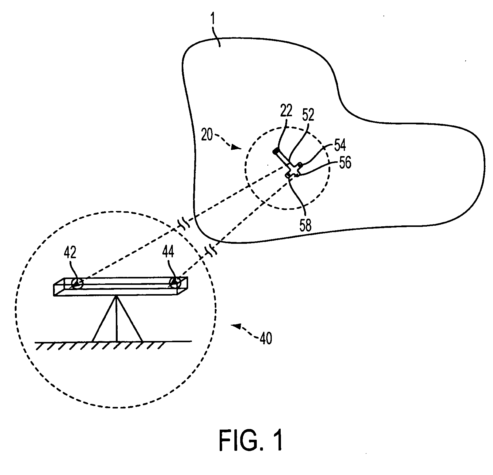
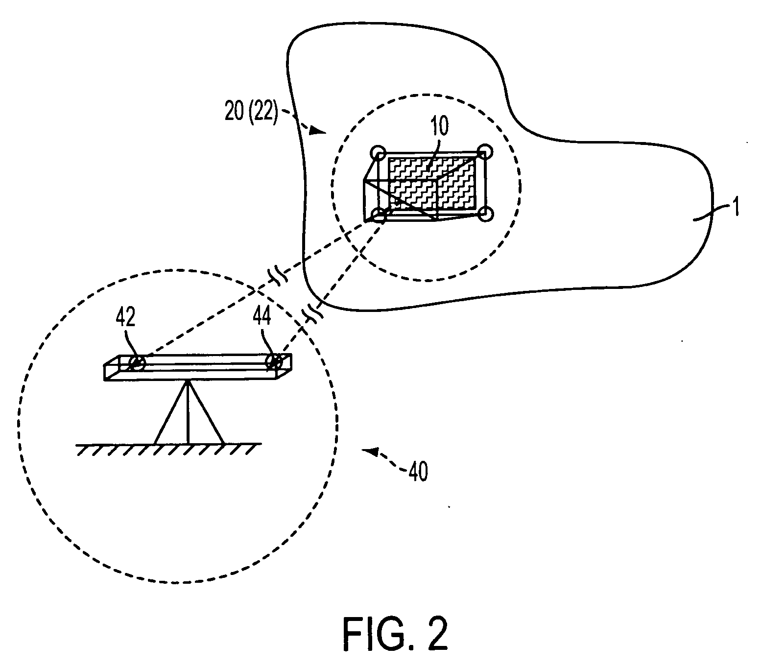
[0052]FIG. 1 shows a component 1 with a sensor unit 20 positioned thereon (in the broken-line circle). A point-by-point test sensor 22 is integrated into the sensor unit 20. It can be an ultrasound sensor. Spaced apart actuators 52, 54, 56, 58 of the triangulation tracking system are applied to the sensor unit 20. Furthermore, the spatially fixed base unit 40 of the triangulation tracking system is shown (in the broken-line circle) in FIG. 1. The base unit 40 of the triangulation tracking system includes two cameras 42 and 44 spaced apart from one another. The cameras 42 and 44 receive the signals transmitted by the actuators 52, 54, 56, 58. The position of the sensor unit 20 and thus the position of the test sensor 22 in the spatially fixed coordinate system of the base unit 40 of the triangulation tracking system can be determined from the signals received, from the known spatial position of the cameras and from the known relative position of the actuators on the sensor unit.

[005...


PUM


Abstract

A method of testing a component, wherein the component is sensed using a test sensor whose position is tested and an apparatus for the carrying out of the method.

Description

CROSS REFERENCE TO RELATED APPLICATIONS [0001] This application claims priority to German Patent Application Serial No. DE 102004061338.9 filed Dec. 20, 2004, which is hereby incorporated by reference in its entirety for all purposes. [0002] 1. Field [0003] The present disclosure relates to a method of testing a component and to an apparatus for carrying out the method. [0004] 2. Background and Summary [0005] Different methods of testing components are already known. With the already known methods, the component structure or the component surface can be examined or tested, for example, for damage or inhomogeneities. EP-1 284 409 A1, for example, describes a shearographic test method in which different load states of the component are measured interferometrically. The different load states can be established by thermal radiation. Interferometric images are recorded in the different load states using a camera. Irregularities in the component structure can be visualized by subtraction ...

Claims


Application Information

Patent Timeline
IPC IPC(8): G01R31/08G05B19/18G08B21/00G01M99/00
CPCG01B11/002G01C11/00G01S5/163
Inventor STEINBICHLER, MARCUSBERGER, ROMANCOLLREP, JORGHUBER, RAINER
Owner STEINBICHLER OPTOTECHN
Learn More