
Multiplexers employing bandpass-filter architectures

a filter architecture and multiplexer technology, applied in the field of multiplexers, can solve the problems of interference with the desired operation of the communications system, and signals at undesired frequency bands being passed

Active Publication Date: 2006-07-06
TDK CORPARATION
View PDF45 Cites 71 Cited by
  • Summary
  • Abstract
  • Description
  • Claims
  • Application Information

AI Technical Summary

Benefits of technology

[0023] Additional objects and advantages of the invention will be set forth in part in the description which follows, and in part will be obvious from the description, or may be learned by practice of the invention. The objects and advantages of the invention will be realized and attained by means of the elements and combinations particularly pointed out in the appended claims.

Problems solved by technology

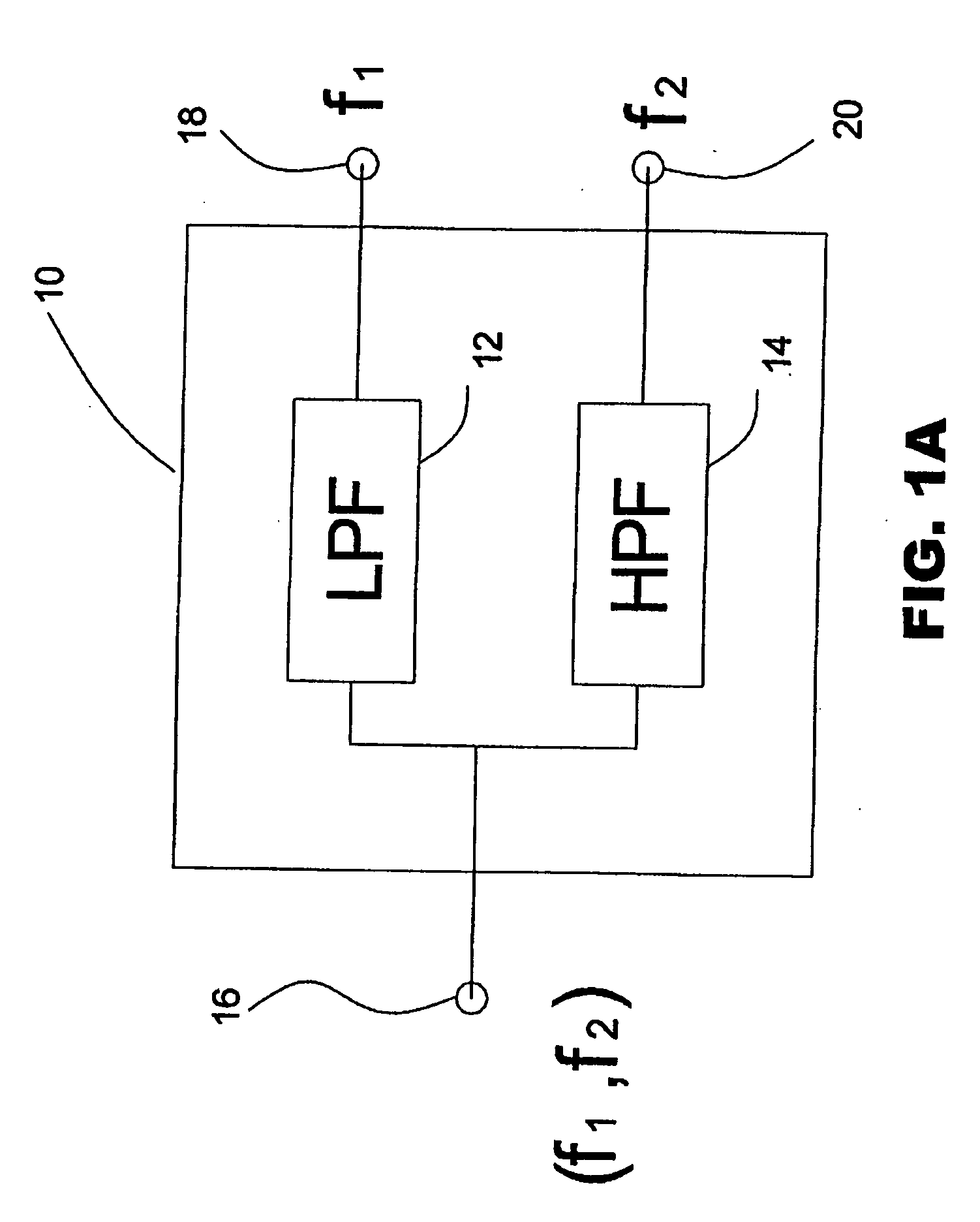
A problem associated with the lowpass-highpass-filter architecture of diplexer 10 is that signals at undesired frequency bands may be passed by lowpass filter 12 and / or highpass filter 14.
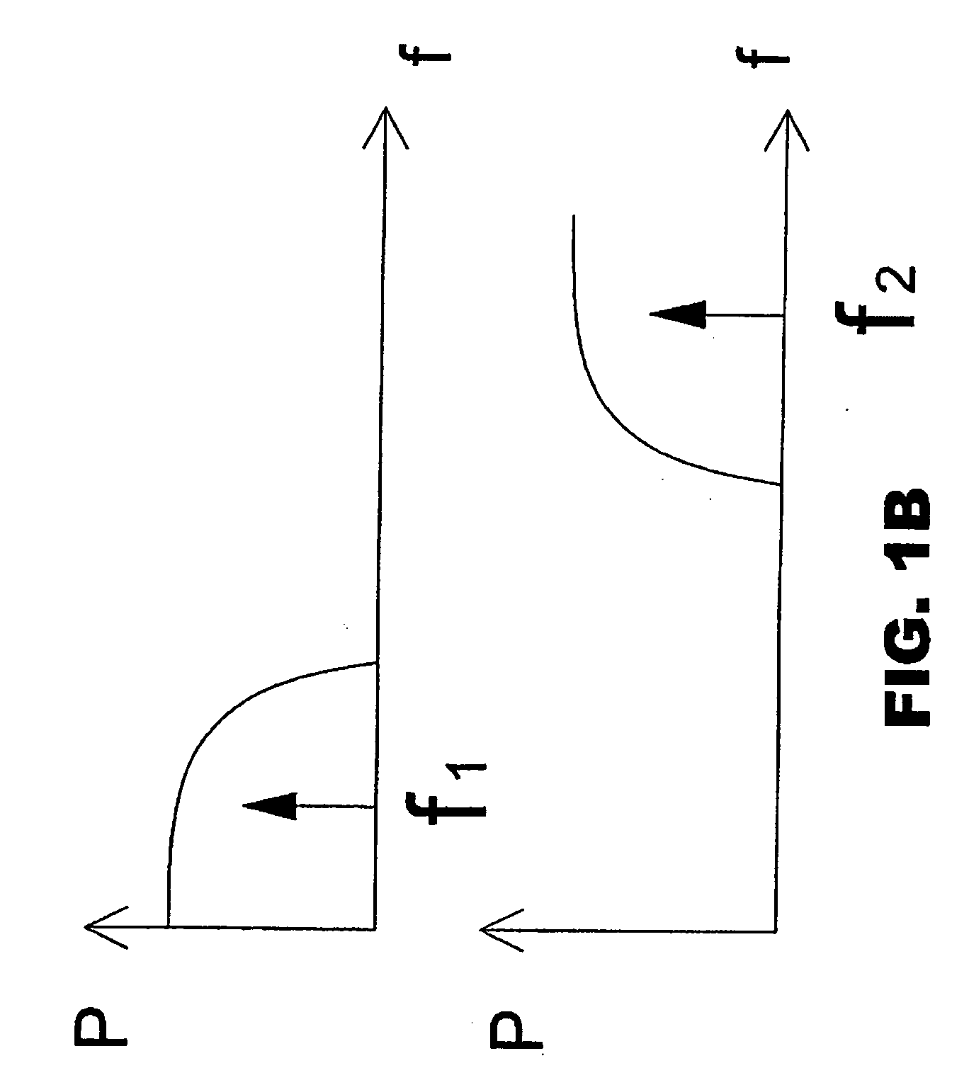
Signals at frequencies passed by lowpass filter 12 that are outside of the desired frequency band around frequency f1 may interfere with the desired operation of the communications system.
Signals at frequencies passed by highpass filter 14 that are outside of the desired frequency band around frequency f2 may also interfere with desired operation of the communications system.
First, when combining bandpass filters to form a duplexer, it is difficult to properly match the filter impedances to obtain the desired performance for each bandpass filter.
Consequently, passband performance may suffer due to the impedance mismatching often found in prior art duplexers employing bandpass-bandpass-filter architecture.
Second, it is difficult to adjust a pole in a bandpass filter to provide a desired attenuation pattern, without simultaneously altering in an undesired manner another portion of the attenuation pattern.
This is because adjustment of a pole in a bandpass filter tends to also move one or more other poles in the bandpass filter, which may tend to alter the attenuation pattern of the bandpass filter in an undesired manner.

Method used


Image

  • Multiplexers employing bandpass-filter architectures
  • Multiplexers employing bandpass-filter architectures
  • Multiplexers employing bandpass-filter architectures

Examples


Embodiment Construction

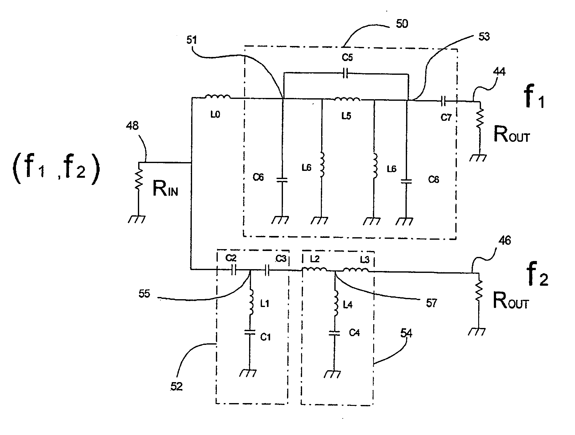
[0048] Reference will now be made in detail to the present exemplary embodiments of the invention, examples of which are illustrated in the accompanying drawings. Wherever possible, the same reference numbers will be used throughout the drawings to refer to the same or like parts.

[0049]FIG. 3 is a block diagram of an embodiment of a communications system 34, in accordance with systems and methods consistent with the present invention. System 34 may comprise any structure for receiving and / or transmitting signals for conveying information of any kind in more than one frequency band. System 34 may include, for example, an antenna 38 coupled to a communications device 36.

[0050] Antenna 38 may comprise any structure, such as one or more antennae, for receiving signals for communications device 36 and / or for transmitting signals from communications device 36.

[0051] Communications device 36 may comprise any structure, which may include one or more devices, for receiving and / or transmit...


PUM


Abstract

A multiplexer, such as a diplexer, is delineated. The multiplexer may be employed in a communications system that may communicate in multiple frequency bands within a predefined range of frequencies, e.g., 2400 MHz-4900 MHz. The communications system may operate in a network, such as a wireless local area network, without significant interference from signals used by a cellular / mobile telephone system. The multiplexer may include multiple channels with bandpass filters that may be formed with lumped inductors and lumped capacitors. In at least one of the channels, the bandpass filter may be formed by combining at least one lowpass filter with at least one highpass filter.

Description

FIELD OF THE INVENTION [0001] The present invention relates to systems employing multiplexers, and more particularly, to systems employing multiplexers with bandpass-filter architectures. BACKGROUND OF THE INVENTION [0002] As used herein and throughout, the terms in quotations below are defined as follows: [0003] a. The term “bandpass filter” may refer to a filter that may pass signals at frequencies within a specified frequency band and may reject signals at frequencies above the specified frequency band, as well as signals at frequencies below the specified frequency band. [0004] b. The term “diplexer” may refer to a three-port frequency-dependent device that may be used as a separator and / or a combiner of signals. [0005] c. The term “highpass filter” may refer to a filter that may pass signals at frequencies above a specified frequency and may reject signals at frequencies below the specified frequency. [0006] d. The term “lowpass filter” may refer to a filter that may pass signa...

Claims


Application Information

Patent Timeline
IPC IPC(8): H03H7/46
CPCH03H7/463H03H2001/0085H03H7/46
Inventor LIU, KAIKOMMRUSCH, RICHARD
Owner TDK CORPARATION
Learn More