Method and system for low-delay video mixing

a video mixer and low-delay technology, applied in the field of video mixers, can solve the problems of degrading image quality, delay between sending and receiving compressed video streams,

Inactive Publication Date: 2006-07-06
NOKIA CORP
View PDF14 Cites 95 Cited by
  • Summary
  • Abstract
  • Description
  • Claims
  • Application Information

AI Technical Summary

Benefits of technology

[0052] According to the present invention, one or more of the first video bistreams comprise a mixed bitstream composed from a plurality of further video bistreams. The procedure further comprises the step of:
[0053] decomposing the mixed bitstream for providing a plurality of component video bitstreams, each of the component video bitstreams corresponding to one of the further video bistreams, so as to allow the component video bitstreams to be combined with one or more other first video bitstreams for generating the second video bitstream.

Problems solved by technology

These decoding and re-encoding steps create a delay between sending and receiving of compressed video streams.
They also degrade the image quality.

Method used


Image

  • Method and system for low-delay video mixing
  • Method and system for low-delay video mixing
  • Method and system for low-delay video mixing

Examples


second embodiment

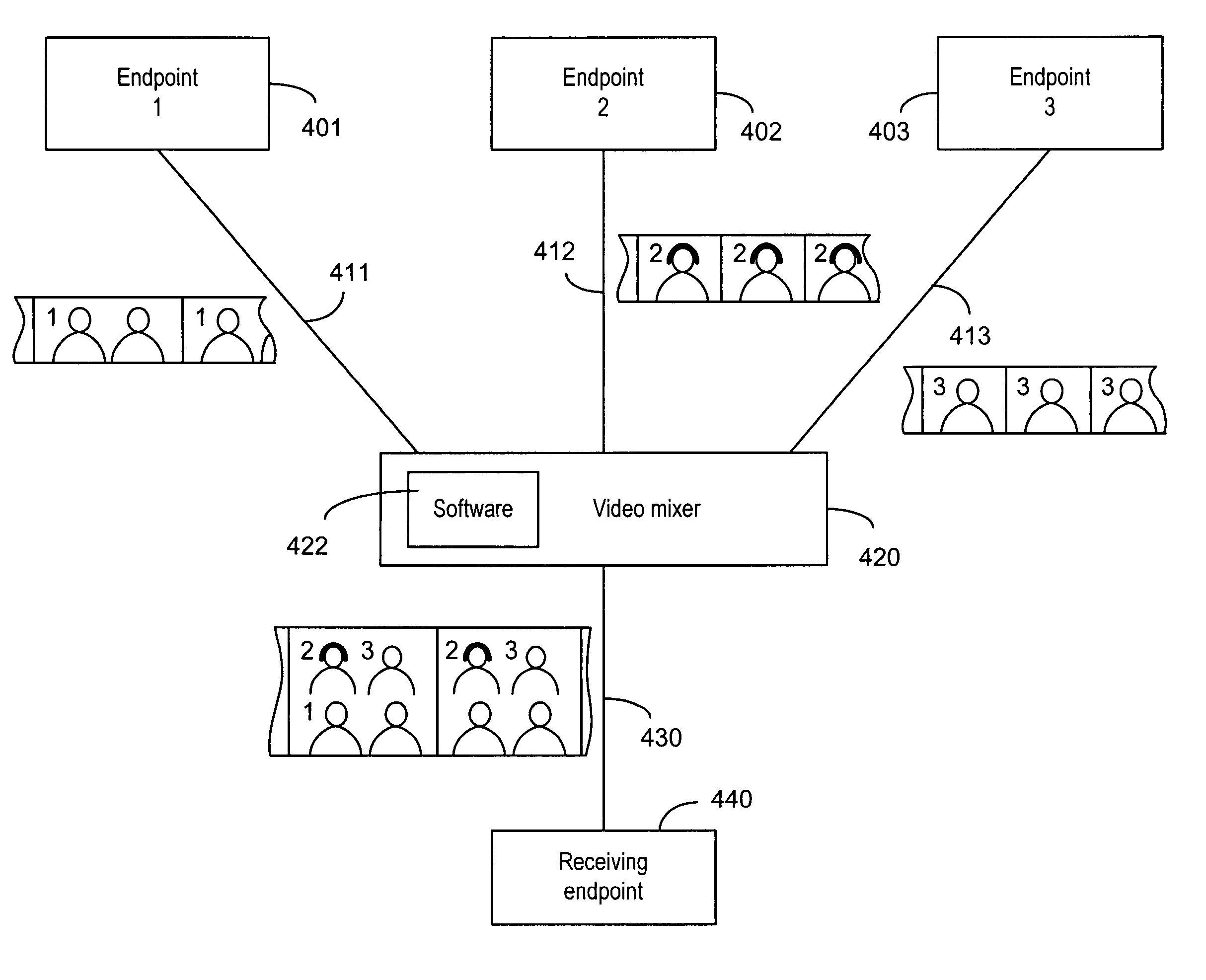
[0130] This embodiment is concerned with mixing of non synchronized sources in a potentially error prone environment. This environment exists when the frame rates of the sending terminals are not the same (e.g. some of the sending terminals are located in the PAL (Phase Alternate Line) domain, and others in the NTSC (National Television Standard Committee) domain, or when frames may be skipped, or when frames are damaged or lost in transmission. The mixing process is considerably more complex.

[0131] In such an environment, during the startup of the conference, the mixer has to signal to the receiving terminal a maximum frame rate that is equal to or higher than the highest frame rate among the rates used by the sending terminals. Alternatively, the mixer can, during the capability exchange, force the sending terminals to a frame rate that is lower than or equal to the frame rate supported by the receiving endpoint.

[0132] Once it is established that the receiving endpoint is “faste...


PUM


Abstract

A method and system for compressed domain video mixing for spatially combining incoming video streams into an outgoing video stream. Using H.264 as an example, each incoming stream is divided into a plurality of slices, each having a plurality of header fields including a first_mb_in_slice header field. Based on the picture format in the outgoing stream, first_mb_in_slice for each incoming stream is modified such that the modified first_mb_in_slice header field is indicative of location in the spatial representation of the outgoing stream at which the slice of the incoming stream is placed. H.264's slice group mechanism is used to map the spatial positions of the second and following macroblocks of the slices to the appropriate locations. If the incoming streams are previously mixed by upstream mixers, a decomposer can be used to separate these mixed streams into component streams before combining them with other incoming streams.

Description

FIELD OF THE INVENTION [0001] The present invention relates to video mixers in real-time sensitive communication systems, such as Multipoint Control Units (MCUs) for video conferencing systems, and to a picture decomposition system and method that constitute the inverse of the mixing process. BACKGROUND OF THE INVENTION [0002] Traditionally, a video conferencing endpoint is designed to connect to another remote video conferencing endpoint in a point-to-point fashion. As depicted in FIG. 1, a sending endpoint 102 comprises a motion video source 101, such as a camera, and an encoder 103 to encode the video images from the video source into a video compressed stream. The video compressed stream is then sent through a network interface 104 over a network 105 to a single receiving endpoint 106. The receiving endpoint 106 comprises a network interface 107, a decoder 108 and a display device 109. The encoder 103 and the decoder 108 are often conforming to one of the known video compression...

Claims


Application Information

Patent Timeline
Patent Type & Authority Applications(United States)
IPC IPC(8): H04L12/16
CPCH04L29/06027H04N7/152H04N19/40H04L65/4038H04N19/174H04L65/605H04L65/765H04L65/1101
Inventor WENGER, STEPHANHANNUKSELA, MISKA
Owner NOKIA CORP
Why Eureka
Try Eureka