Terminal device, base station device, and frequency resource allocation method

a technology of frequency resource allocation and base station, which is applied in the direction of frequency-division multiplex, transmission monitoring, wireless commuication services, etc., can solve the problems of decreasing throughput and achieve the effect of reducing overhead

Inactive Publication Date: 2011-09-15
SOVEREIGN PEAK VENTURES LLC
View PDF12 Cites 52 Cited by
  • Summary
  • Abstract
  • Description
  • Claims
  • Application Information

AI Technical Summary

Benefits of technology

[0017]According to the present invention, the terminal apparatus side autonomously selects a subband according to the interference state, so that it is ...

Problems solved by technology

As a result, SINR (Signal-to-Interference and Nois...

Method used


Image

  • Terminal device, base station device, and frequency resource allocation method
  • Terminal device, base station device, and frequency resource allocation method
  • Terminal device, base station device, and frequency resource allocation method

Examples


embodiment 1

(1) Configuration

[0070]First, the configurations of a base station apparatus (hereinafter simply “base station”) and a terminal apparatus (hereinafter simply “terminal”) according to the present embodiment will be explained. Note that a case will be explained with the present embodiment as an example where an OFDMA scheme is used as an access method.

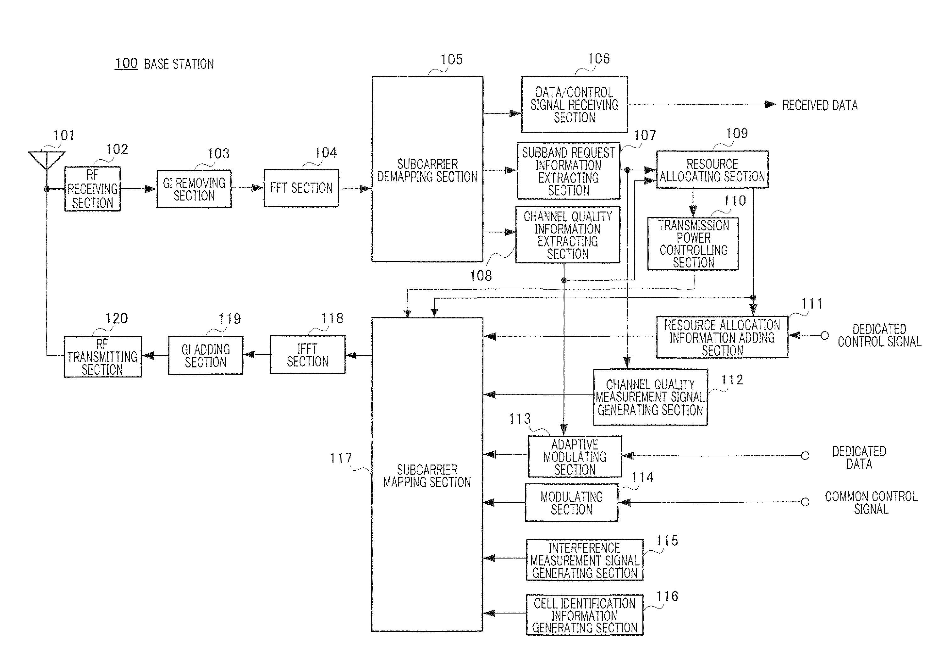
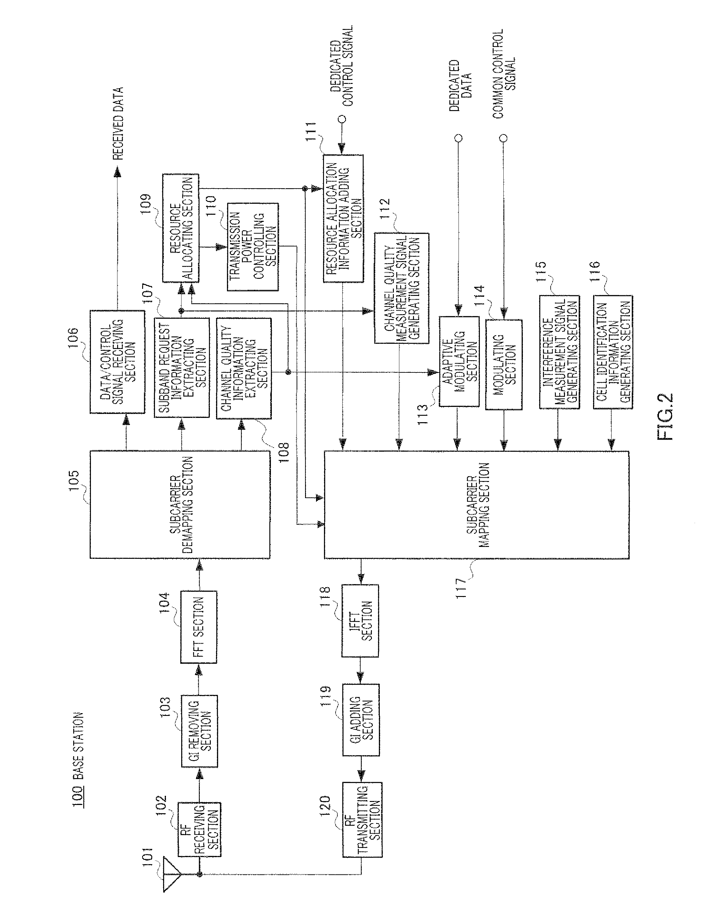
[0071]FIG. 2 shows the configuration of the base station. Base station 100 inputs a signal received at antenna 101, to RF (Radio Frequency) receiving section 102. RF receiving section 102 performs predetermined radio processing such as amplification processing and down-conversion processing of the received signal. GI (Guard Interval) removing section 103 removes a guard interval from the received signal subjected to radio processing, and FFT section 104 transforms the time domain signal into a frequency domain signal. By this means, a signal of each subcarrier is reproduced.

[0072]Subcarrier demapping section 105 sorts a signal mapped on ...

embodiment 2

[0157]With the present embodiment, another method of selecting subband indices (“SBIs”) in a terminal will be explained. Although, with Embodiment 1, relative positions of subbands are determined according to the interference state (D / U) in step 1 of selecting subbands, selection is performed in step 1 of the present embodiment in a different way from Embodiment 1.

[0158]With the present embodiment, the subband selecting section of terminal 200 selects a subband by executing roughly following two steps.

[0159]Step 1: Determine Relative Positions of Subbands

[0160]Based on an inter-cell interference state (D / U) calculated from the output of the interference state detecting section and information about a cell identifier outputted from the cell identifying section, the relative positions of subbands are determined.

[0161]To be more specific, first, based on the inter-cell interference state (D / U) calculated from the output of the interference state detecting section, the absolute value |f...

embodiment 3

[0173]With the present embodiment, a subband control method that is suitably applied to a mobile communication system including terminals of low capability will be explained.

[0174]The next-generation mobile communication system allows high speed data communication exceeding 100 Mbps by widening an operating frequency bandwidth. In this case, taking into account cost requirement, power consumption requirement and backward compatibility requirement of terminals, it is assumed that terminals having different levels of reception capability (i.e. modulation schemes that can be supported, coding schemes, the maximum bandwidth that can be received and the maximum bandwidth that can be transmitted) are provided depending on use of terminals without equipping all terminals with the functions of full specifications. Therefore, the next-generation mobile communication system must efficiently accommodate terminals having various levels of reception capability.

[0175]The present embodiment presen...


PUM


Abstract

It is possible to realize reduction of inter-cell interference by an adaptive FFR with a low delay. A terminal (200) includes: an interference condition detection unit (209) which detects an interference condition of other cell to the local cell; a cell identification unit (210) which acquires signals for cell identification of each base station; and a sub-band selection unit (211) which selects a sub-band used for the downstream line transmission to the local station according to the interference condition detected by the interference condition detection unit (209) and the signals for cell identification of each base station obtained by the cell identification unit (210). Thus, the terminal (200) can autonomously select a small sub-band of inter-cell interference and to realize reduction of the inter-cell interference by the adaptive FFR with a low delay.

Description

TECHNICAL FIELD[0001]The present invention relates to a terminal apparatus, a base station apparatus and a frequency resource allocation method for reducing inter-cell interference in a cellular mobile communication system.BACKGROUND ART[0002]A cellular mobile communication system has a parameter referred to as “frequency reuse factor (“RF”).” In case where this reuse factor (“RF”) is 1, the same frequency is used in all sectors. In such a case, a user (i.e. terminal apparatus) at a cell edge in the boarder between neighboring cells receives interference from a neighboring cell. As a result, SINR (Signal-to-Interference and Noise Ratio) deteriorates, thereby decreasing the throughput.[0003]By contrast with this, in case where, for example, the reuse factor (“RF”)=1 / 3, three frequencies are used to perform frequency allocation between cells or between sectors such that the same frequency is not used between neighboring cells or between sectors. In this case, although SINR improves, f...

Claims


Application Information

Patent Timeline
IPC IPC(8): H04J1/00
CPCH04J11/005H04L5/0005H04L5/0037H04L5/006H04B17/382H04L5/0094H04W16/12H04W72/082H04L5/0062H04W72/541
Inventor KISHIGAMI, TAKAAKISUMASU, ATSUSHIYOSHII, ISAMUIMAI, TOMOHIRO
Owner SOVEREIGN PEAK VENTURES LLC
Why Eureka
Try Eureka