Eureka AIR delivers breakthrough ideas for toughest innovation challenges, trusted by R&D personnel around the world.

Mismatched delay based interference cancellation device and method

a delay-based interference and delay technology, applied in the direction of transmission, electrical equipment, etc., can solve the problems of high received bit-error rate, degradation of signal error vector magnitude, etc., and achieve the effect of reducing the interference signal

Inactive Publication Date: 2011-03-17
UBIDYNE
View PDF5 Cites 56 Cited by
  • Summary
  • Abstract
  • Description
  • Claims
  • Application Information

AI Technical Summary

Benefits of technology

[0010]The interference signal cancellation device can be used in connection with a software-defined radio system, because the substantially linear behaviour of the first signal path and the second signal path prevents excessive intermodulation. Thus, the frequency range covered by the disturbed signal is not or at least only to a small extent, enlarged, diminished or shifted. This preservation of the covered frequency range usually reduces problems in a subsequent analogue-to-digital converter, such as increased noise level. A non-linearity in the first signal path and / or the second signal path would typically lead to a degradation of the error vector magnitude of the signal. A consequence of a high error vector magnitude is often a high received bit-error rate. Reducing or eliminating the non-linearities in the first signal path and the second signal path avoids these problems.
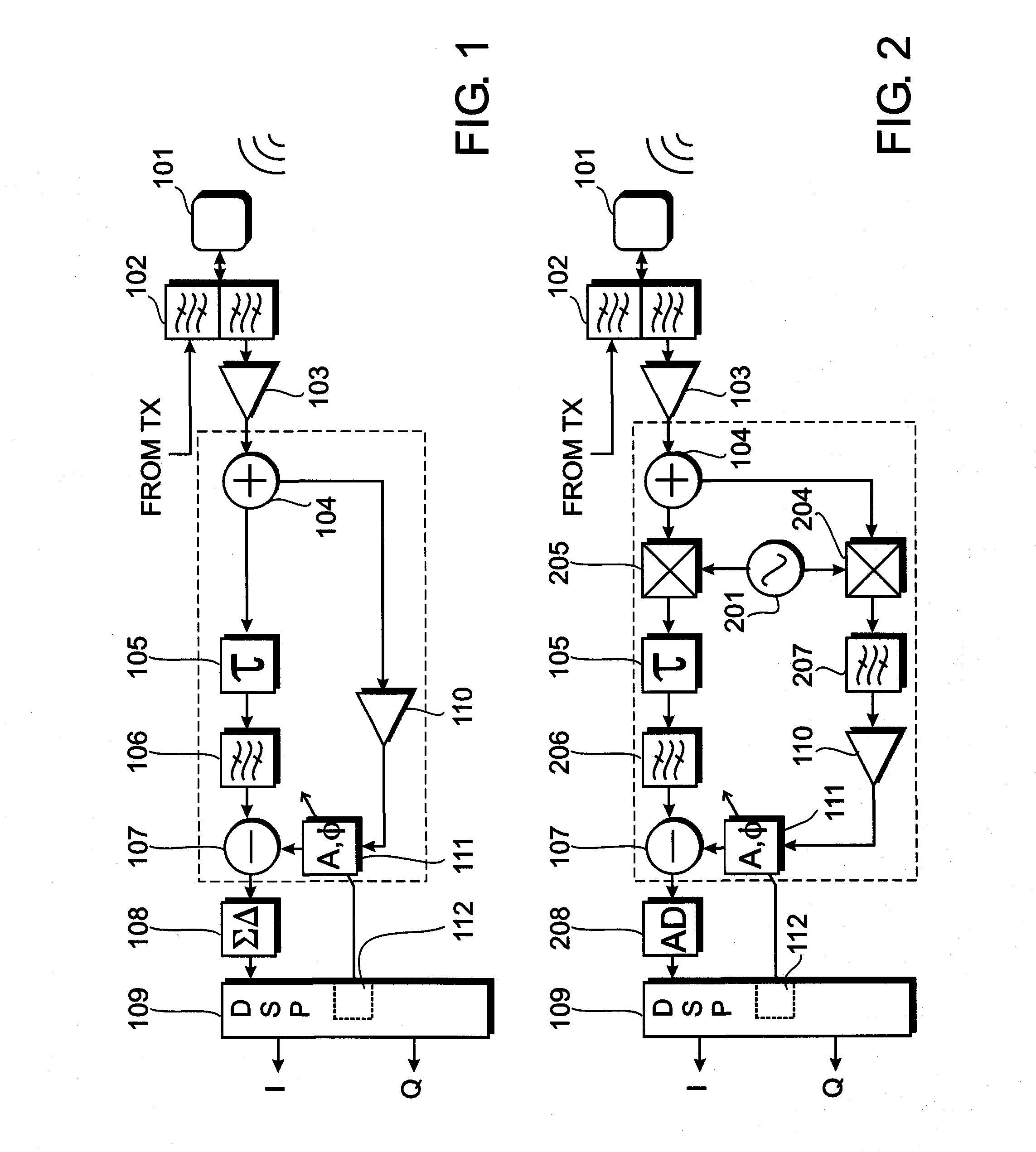
[0012]At least one of the first signal path and the second signal path may comprise a filter. In a wideband signal it is possible that the relative delay causes a destructive superposition not only for the interference signal, but also at other frequencies. Depending on the application, it may not be desirable to cancel portions of the wideband signal at those frequencies where destructive superposition occurs. For example, it could be that a payload signal of another channel happens to be at a frequency that is affected by destructive superposition due to the relative delay. The filter in at least one of the first signal path and the second signal path is able to prevent such destructive superposition.
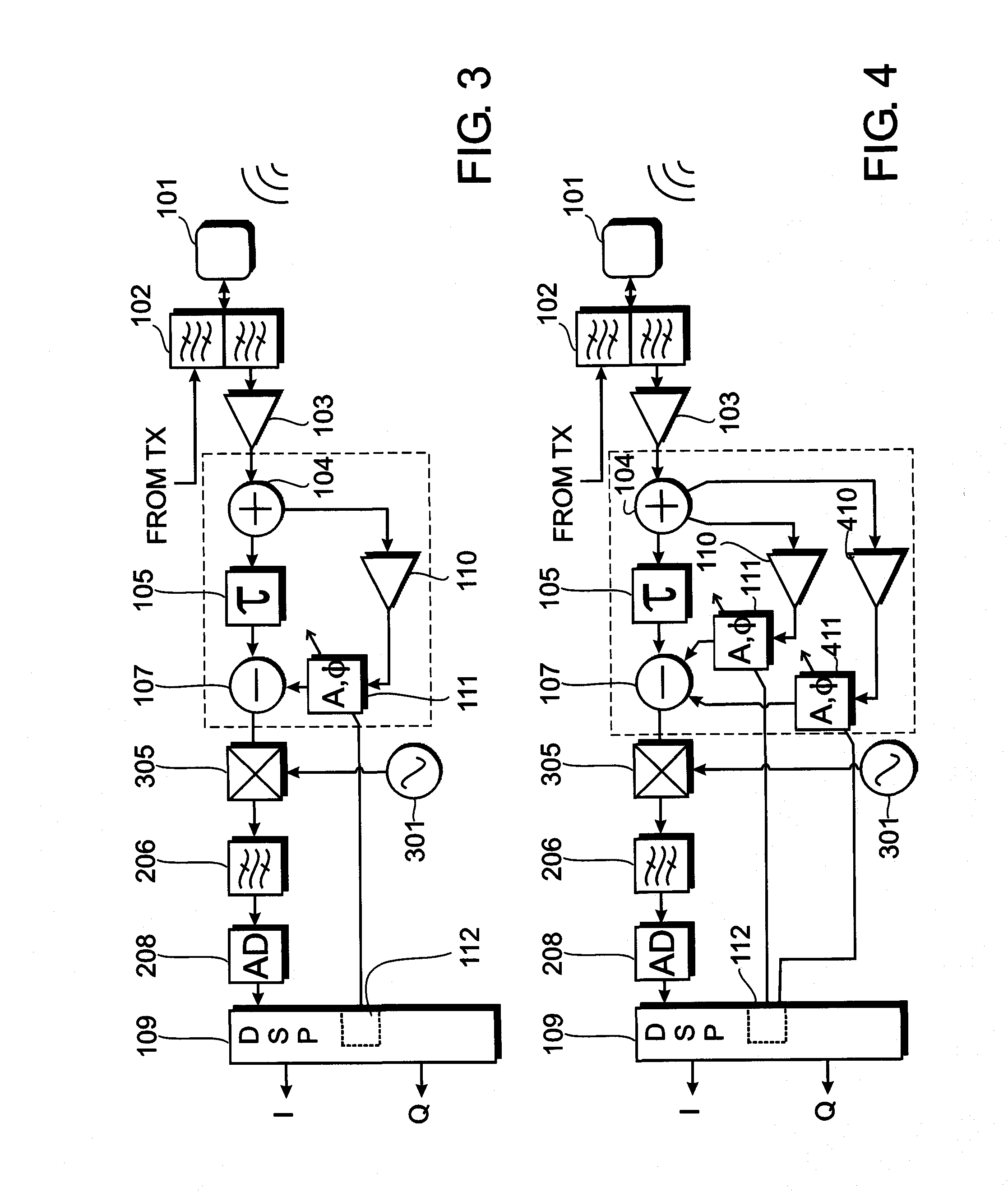
[0018]It would be desirable that in a receiver structure having a plurality of similar or identical receive paths, such as in a receiver structure connected to an antenna array, interference signal cancellation could be achieved for all of the receive paths and with little structural overhead. This aspect and / or possible other aspects are addressed by the cancellation controller controlling a plurality of at least one of gain controllers and phase controllers, each one of the gain controllers or phase controllers being part of an individual receive path in a group of similar or identical receive paths. For example, if the group of similar or identical receive paths is connected to the antenna array, the relative phase of the interference signal within the individual receive path depends on the location of the interference signal source relative to the antenna array. The same is true for the phase of the wanted signal within the individual receive path and a location of the source of the wanted signal relative to the antenna array. The proposed arrangement allows an adjustment of the interference signal's amplitude and phase independent from any gain and phase adjustments for the desired signal.
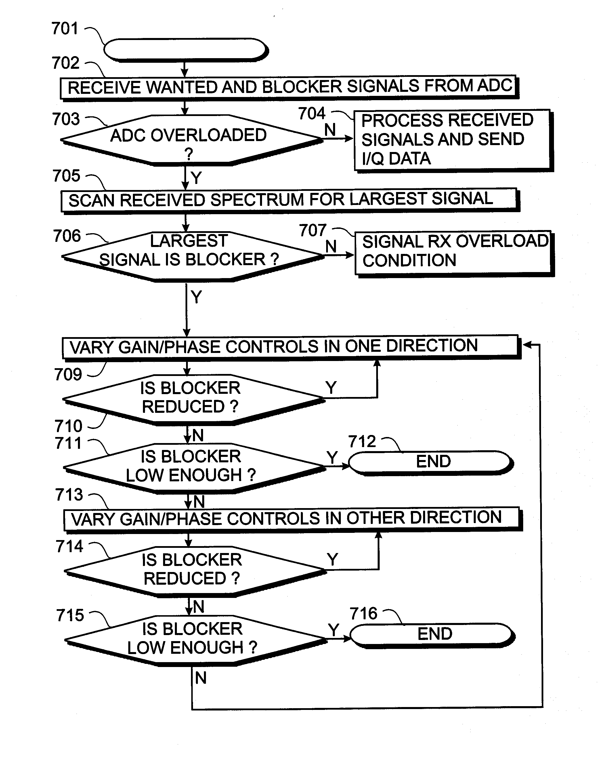
[0023]The present disclosure further provides a method for interference cancellation on a disturbed signal comprising an interference signal. The method comprises splitting the disturbed signal into a first signal and a second signal, time delaying at least one of the first signal and the second signal by a relative delay between the first signal and the second signal, and combining the first signal and the second signal for substantially reducing the interference signal within the disturbed signal due to the introduced delay. The first signal and the second signal undergo substantially only linear processing between splitting and combining.

Problems solved by technology

A non-linearity in the first signal path and / or the second signal path would typically lead to a degradation of the error vector magnitude of the signal.
A consequence of a high error vector magnitude is often a high received bit-error rate.

Method used


Image

  • Mismatched delay based interference cancellation device and method
  • Mismatched delay based interference cancellation device and method
  • Mismatched delay based interference cancellation device and method

Examples


Embodiment Construction

[0037]The invention will now be described on the basis of the drawings. It will be understood that the embodiments and aspects of the invention described herein are only examples and do not limit the protective scope of the claims in any way. The invention is defined by the claims and their equivalents. It will be understood that features of one aspect can be combined with a feature of a different aspect or aspects.

[0038]FIG. 1 shows a receiver arrangement or a receive path that may be used in a base-station of a mobile communications network. A signal from a remote transmitter is received at an antenna 101. The antenna 101 is connected to a duplex filter 102 that separates a transmission path from the receive path in the frequency domain. Instead of a duplex filter, other techniques may be used, such as a circulator or time multiplexing. The signal arriving from the transmission path is illustrated as the input to the upper part of the duplex filter 102. The lower part of the duple...


PUM


Abstract

An interference signal cancellation device comprises a signal splitter, a delay element and a signal combiner. The signal splitter distributes a disturbed signal to a first signal path and a second signal path. The delay element is situated in at least one of the first signal path and the second signal path for introducing a relative delay between a first signal in the first signal path and a second signal in the second signal path. The signal combiner combines the first signal and the second signal. An interference signal within the disturbed signal is substantially reduced within the signal combiner. A method for interference signal cancellation is also proposed. Furthermore, a computer program product with instructions for the manufacture and a computer program product enabling a processor to carry out the method for interference signal cancellation are also proposed.

Description

CROSS REFERENCE TO OTHER APPLICATIONS[0001]The present application is related to a patent application entitled “Frequency shifting based interference cancellation device and method” (Attorney Docket No. 4424-P04911US0) filed concurrently herewith. The entire disclosure of the foregoing application is incorporated herein by reference.FIELD OF THE INVENTION[0002]The field of the present invention relates to an interference signal cancellation device, used for example, in a receiver used in a base transceiver station (BTS) of a mobile communications network. The field of the present invention further relates to a method for interference cancellation on a disturbed signal comprising an interference signal. The field of the present invention also relates to a computer program product enabling a foundry to carry out the manufacture of an interference cancellation device, and to a computer program product enabling a processor to carry out the method for interference cancellation.BACKGROUND...

Claims


Application Information

Patent Timeline
IPC IPC(8): H04B1/10
CPCH04B1/1036
Inventor KENINGTON, PETERNEUMANN, DIRK
Owner UBIDYNE
Why Eureka
Eureka Blog
Learn More