Gas circuit and pilot light system for cooking range

a technology of pilot light and cooking range, which is applied in the direction of gaseous heating fuel, combustion types, stoves or ranges, etc., can solve the problems of piezo electric and spark ignition systems that can be fouled, difficulty in spark and piezo pilot systems, and common spills and boilovers

Active Publication Date: 2006-07-06
PREMARK FEG L L C
View PDF45 Cites 13 Cited by
  • Summary
  • Abstract
  • Description
  • Claims
  • Application Information

AI Technical Summary

Benefits of technology

[0008] The present invention provides a gas circuit for a cooking range with pilot tubes supported on the burner assemblies, and quick connect couplings attaching the tubes to a gas manifold so that removal of the burner assemblies also leads to removal of the pilot tubes. A shut-off valve may terminate gas flow to the burners and pilot lights on the range, but not in the oven.

Problems solved by technology

However, in commercial kitchens where ranges are used almost continuously, and hundreds of meals may be prepared in a short time, difficulties have been encountered with spark and piezo pilot systems.
In commercial kitchens with large quantities of food being prepared in what can be a somewhat hectic environment, spills and boil-overs are common occurrences.
Piezo electric and spark ignition systems can be fouled by spillage or boil-overs and thereafter may not work properly.
As a result, the burners of a cook top often remain on during the entire kitchen operating time, wasting great amounts of gas.
Thus, the pilot lights are not removed easily, and often are left in place when the burner assemblies are removed for cleaning.
Even when the grates and burners are removed, cleaning around the pilot light system can be difficult in that they are connected in place, more or less permanently.
Consequently, food spilled onto and beneath the pilot light gas tubes can be difficult to clean.
Although standing pilot light flames are small, when burned continuously the amount of fuel consumed can be significant.
Burning pilot lights when a kitchen is closed and not in use is wasteful and expensive.
However, known gas circuits for ranges including ovens have used only a single shut-off valve for the entire appliance.
The shut-off is on the back of the appliance, and is difficult to access.
Further, shutting off all pilot lights including the oven pilot light can be inconvenient, in that oven burner pilot lights are often difficult to re-light due their relative inconvenient location.

Method used


Image

  • Gas circuit and pilot light system for cooking range
  • Gas circuit and pilot light system for cooking range
  • Gas circuit and pilot light system for cooking range

Examples


Embodiment Construction

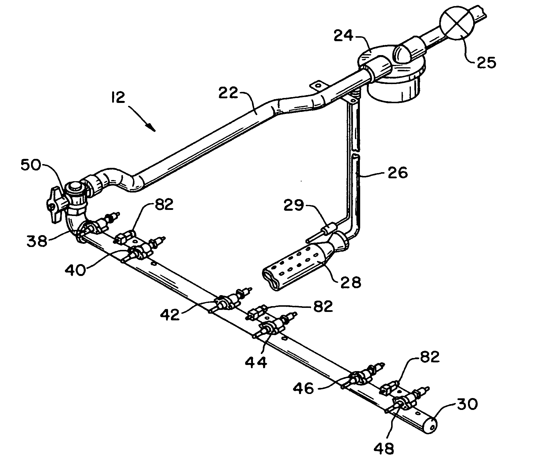
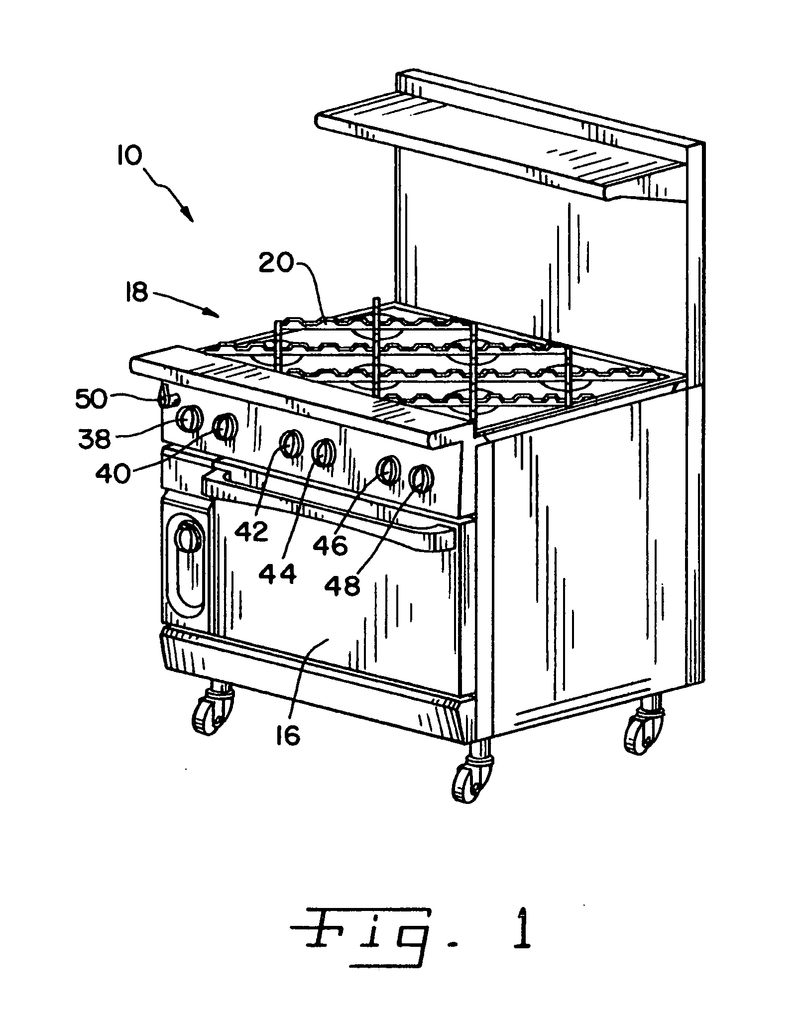
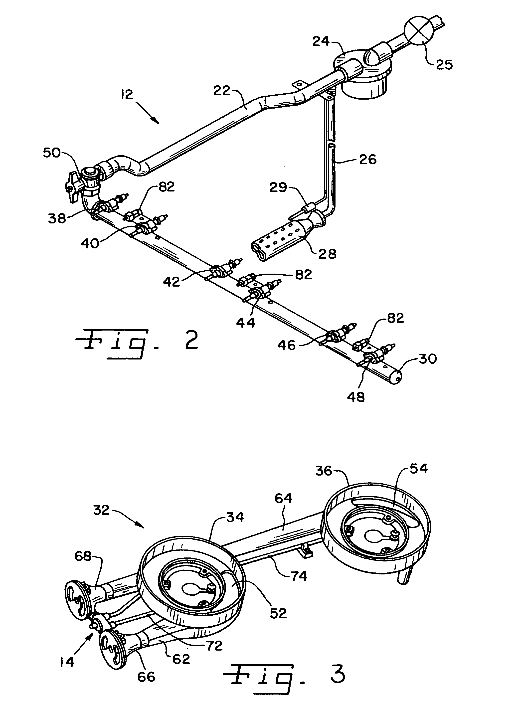
[0022] Referring now more specifically to the drawings and to FIG. 1 in particular, numeral 10 designates a cooking range having a gas circuit 12 (FIG. 2) including a pilot light system 14 (FIG. 4) in accordance with the present invention. The present invention is useful for commercial ranges and residential ranges, and the particular configuration of range 10 shown in FIG. 1 is merely exemplary.

[0023] Range 10 further includes an oven 16 and a cook top 18. Cook top 18 has grates 20 for supporting cooking vessels (not show) such as pots, pans, griddles and the like.

[0024] Range 10 is a gas fired range, having gas circuit 12 for supplying combustible gas to the various cooking locations on cook top 18, and to heat the interior of oven 16. Circuit 12 includes a main gas line 22 connected to a gas fuel source such as, for example a propane tank (not shown) or a natural gas line from a natural gas utility. In one embodiment, the gas line is connected to the fuel source via a hose (not...


PUM


Abstract

A gas circuit with a pilot light system for ranges includes pilot tubes from a gas manifold to burner assemblies. Quick connect couplings are provided between the pilot tubes and manifold so that the pilot tube can be removed easily. Two or more tubes can be connected to a single coupling. A master shutoff interrupts flow to the cooktop without interrupting flow to the oven.

Description

FIELD OF THE INVENTION [0001] The present invention generally relates to gas-fired appliances and, more particularly, to gas supply circuits for cooking ranges and commercial cook tops having pilot lights for igniting burners. BACKGROUND OF THE INVENTION [0002] Gas-fired cooking ranges are used in both residential and commercial kitchens. A basic design for a gas-fired range includes a gas supply source, a manifold and one or more burner assemblies for receiving gas from the gas supply source. Burner assemblies are provided at one or more location for cooking on top of the range, and in an enclosed oven for baking. A control valve is used for each burner assembly, to initiate and terminate gas flow from the manifold to the burner assembly, and to control the gas flow to regulate the intensity of the flame at the burner assembly. When gas flow is initiated to the burner, an ignition source is required to ignite the gas flow. A known ignition system includes an open-flame, standing pi...

Claims


Application Information

Patent Timeline
Patent Type & Authority Applications(United States)
IPC IPC(8): F23Q9/00F24C3/00
CPCF24C3/103F24C3/126Y10T137/87877
Inventor CZAJKA, CHARLESVINCENTY, PHILIP JOSEPH PIODIGGINS, RANDALL B.
Owner PREMARK FEG L L C
Why Eureka
Try Eureka