
Coaxial connectors

a technology of coaxial connectors and connectors, which is applied in the direction of television connectors, two-part coupling devices, electrical appliances, etc., can solve the problems of deterioration of the electrical contact between the outer cable conductor and the head portion in time, and achieve excellent cable retention and enhance the effect of sealing

Inactive Publication Date: 2006-07-06
SEE S P R L
View PDF9 Cites 7 Cited by
  • Summary
  • Abstract
  • Description
  • Claims
  • Application Information

AI Technical Summary

Benefits of technology

"The invention is a connector for coaxial cables that has several technical effects. First, it includes a clamping member that compresses a portion of the exterior conductor, which results in a hardening of the material that prevents further compression. This allows the connector to adapt to changes in pressure and maintain a good electrical contact over a long period of time. Second, the connector includes a permanently deformable split ferrule that tightens the cable and prevents it from being pulled out. Third, the connector includes O-rings that are compressed both radially and axially to enhance the seal against moisture. Overall, the invention provides a connector that can adapt to different types of coaxial cables and ensure a reliable and durable electrical connection."

Problems solved by technology

The coaxial connector known from EP-A-897 202 however has the disadvantage that the electrical contact between the outer cable conductor and the head portion may deteriorate in time.

Method used


Image

  • Coaxial connectors
  • Coaxial connectors
  • Coaxial connectors

Examples


Embodiment Construction

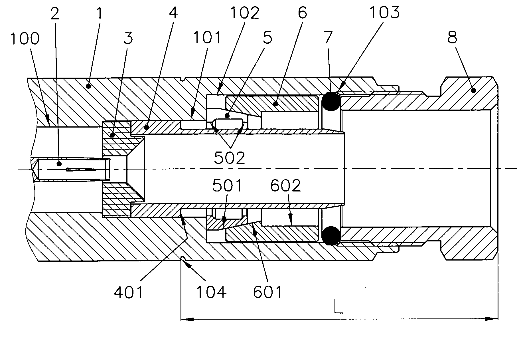
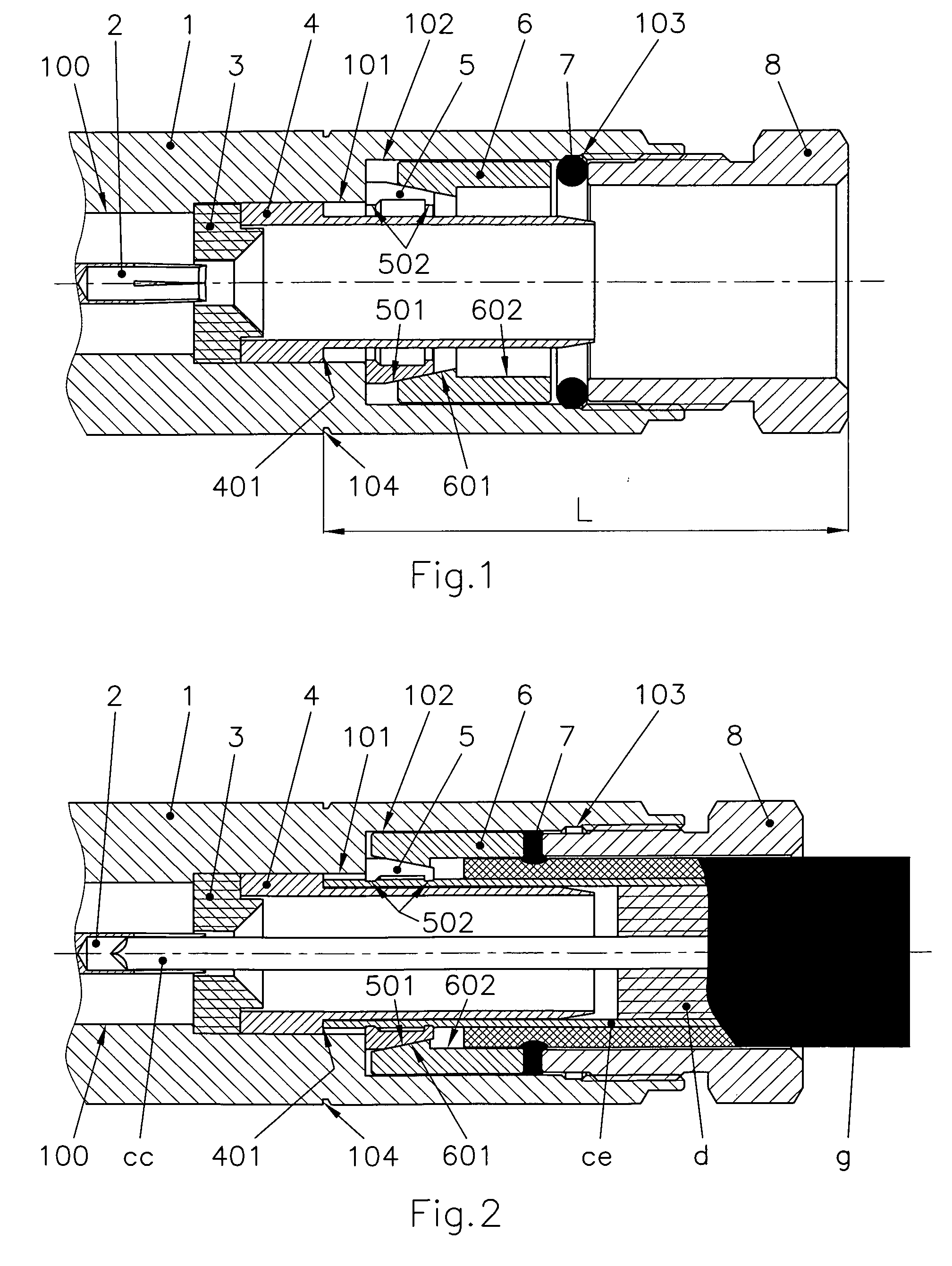
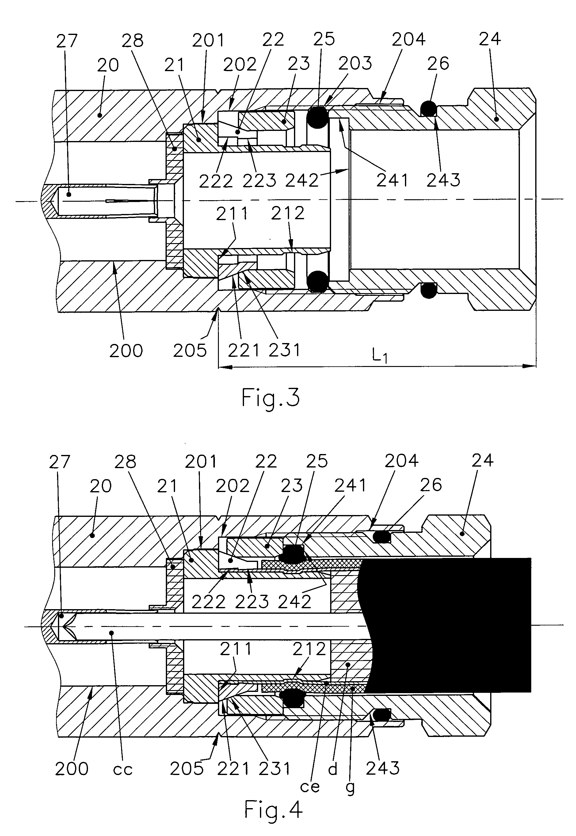
[0029] The coaxial connectors shown in the figures are intended for mounting on a coaxial cable which comprises a central conductor cc, a dielectric d surrounding the central conductor cc, an exterior conductor ce, cet, cef surrounding the dielectric d and an outer insulation g. As appears from the figures, solutions are presented for different types of coaxial cables which may be used in telecommunication, television distribution and other applications, particularly for connectors whose mounting cannot be effected by welding. In this case a plurality of categories exist: connectors which are mounted in the field, connectors for cables of large dimensions, connectors for cables with conductors whose metal is unsuitable for welding or for cables whose dielectric cannot resist the temperature of welding etc.

[0030] The coaxial connectors have to fulfil one or more of the following conditions: decent fixing on the cables, resistance to corrosion, and assuring good electric contacts. Th...


PUM


Abstract

A coaxial connector mountable on an end of a coaxial cable having a central conductor (cc) and an exterior conductor (ce), the connector comprising a first conductive contact element (2; 27; 38; 40) for contacting the central conductor (cc), a second conductive contact element (4; 21; 302; 411) for contacting the exterior conductor (ce) electrically isolated from the first contact element, a clamping member (5; 22; 42) opposing the second contact element for clamping the exterior conductor against the second contact element and a force applying member (6; 23; 441) for forcing the clamping member and the second contact element towards each other, wherein the second contact element and / or the clamping member comprise at least one deforming member (502; 222-223; 423-424) for deforming the exterior conductor (ce) under influence of the force applying member, wherein each deforming member (502; 222-223; 423-424) is constructed in a material with a predetermined hardness above that of the material of the exterior conductor and has a predetermined shape for hardening a portion of the exterior conductor to such an extent that it becomes substantially fully elastic.

Description

BACKGROUND OF THE INVENTION [0001] 1. Field of the Invention [0002] The present invention relates to coaxial connectors mountable on an end of a coaxial cable having a central conductor and an exterior conductor. [0003] All the materials which are used in fabricating coaxial cables, the metals as well as the plastics, are non-elastic materials. The fixing onto the cable, the sealing and the electric contacts are functions which are realised by forces between the elements of the cable and the elements of the connector during the mounting of the latter on the cable. The majority of existing connectors use rigid elements for applying the necessary forces for realising one or more of the functions, which leads to a material flow which consists of a cold deformation for eliminating mechanical stress. The forces diminish to an extent which is insufficient for the respective function. An other problem of existing connectors is the use of an internal threaded part for holding the exterior c...

Claims


Application Information

Patent Timeline
Patent Type & Authority Applications(United States)
IPC IPC(8): H01R9/05
CPCH01R24/564H01R2103/00H01R2201/18
Inventor ANDREESCU, PAUL
Owner SEE S P R L
Learn More