Louver heat vent for chassis of computer

Inactive Publication Date: 2006-07-06
SU CHI MIN
View PDF21 Cites 16 Cited by
  • Summary
  • Abstract
  • Description
  • Claims
  • Application Information

AI Technical Summary

Benefits of technology

[0006] The main objective of the present invention is to provide a louver heat vent for a chassis of a computer w

Problems solved by technology

However, the structural integrity requirements of the chassis limit the sizes of the multiple holes and accordingly, the effectiveness of heat

Method used


Image

  • Louver heat vent for chassis of computer
  • Louver heat vent for chassis of computer
  • Louver heat vent for chassis of computer

Examples


Example

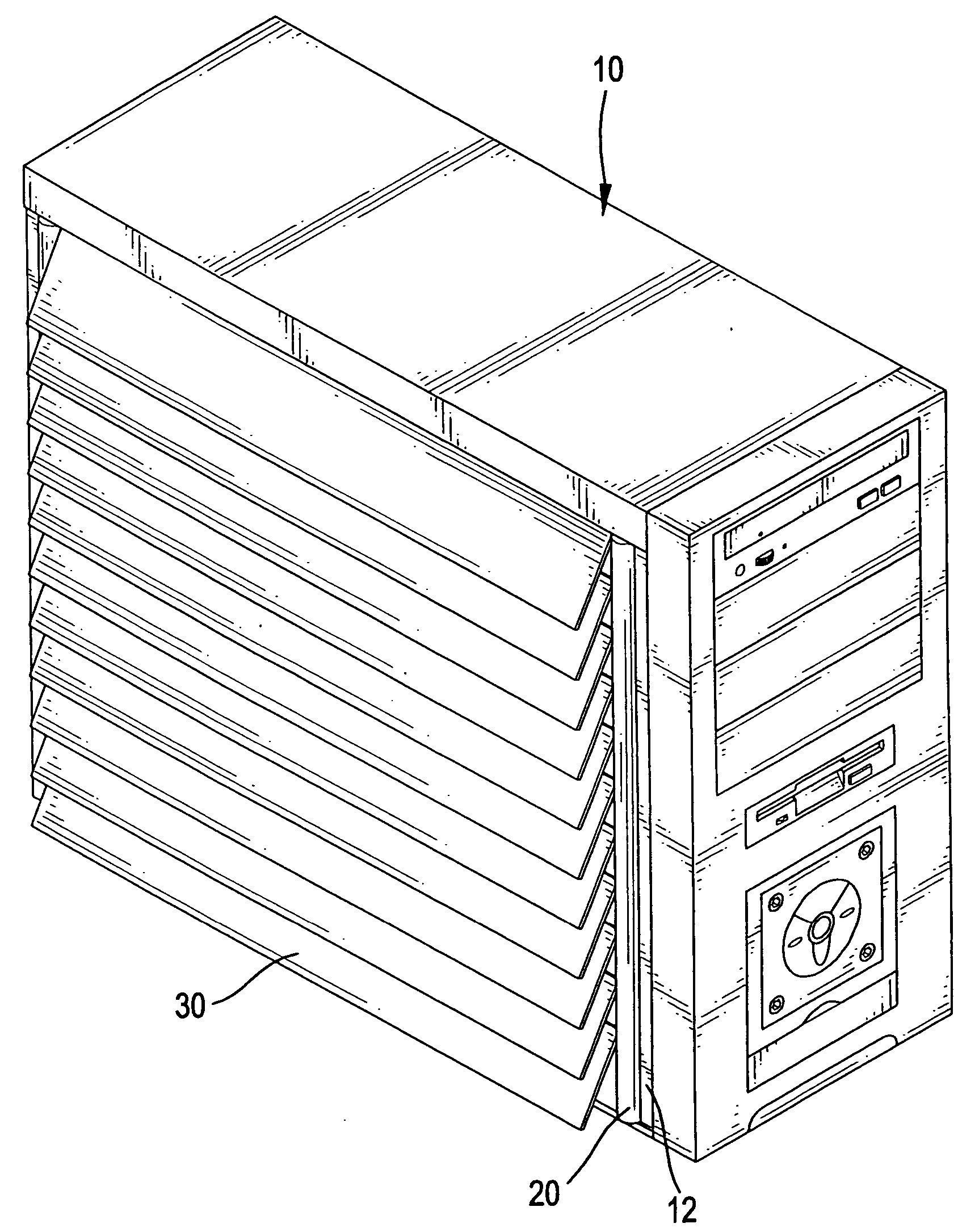
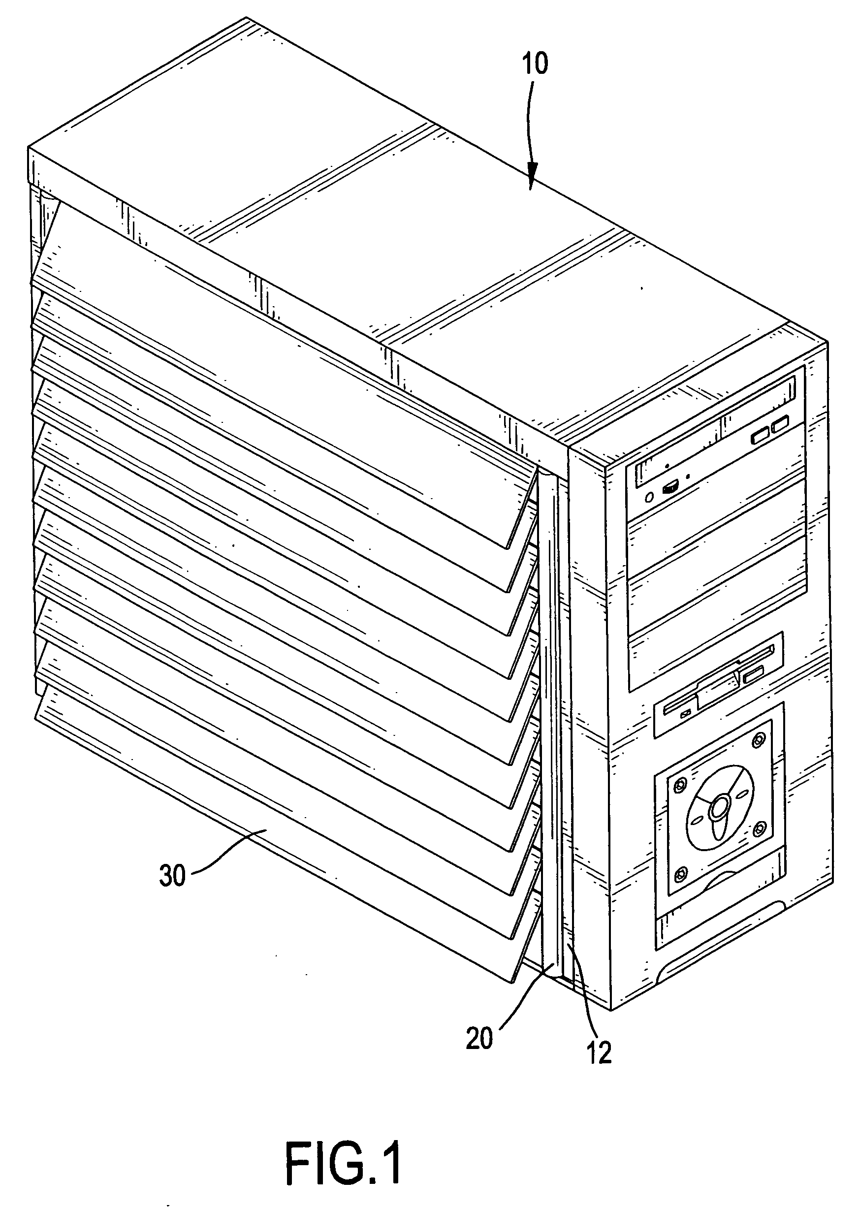
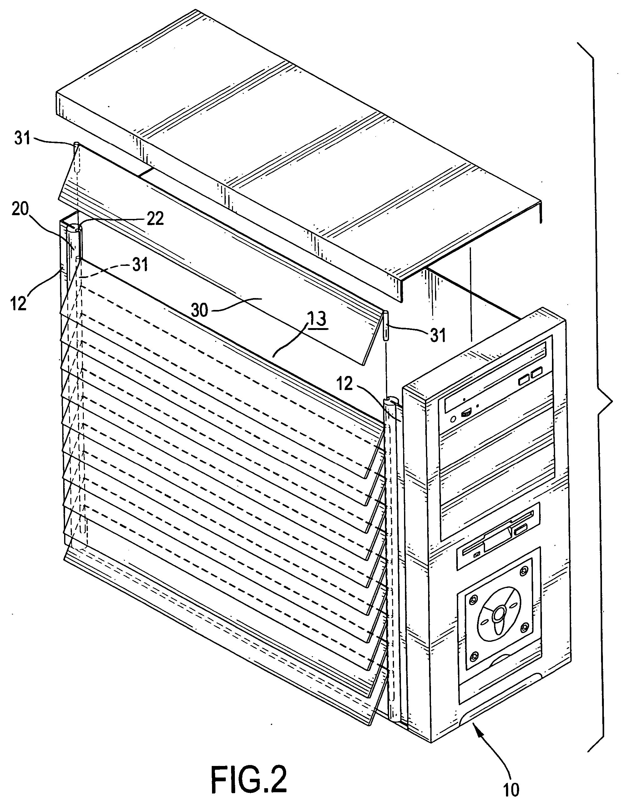
[0013] With reference to FIGS. 1-2, a chassis (10) of a computer comprises a casing (12) with three walls forming a U-like structure when viewed from above, and an opening (13) defined between distal edges of a first and third of the three walls. With reference to FIGS. 2-4, a first preferred embodiment of a louver heat vent for a chassis of a computer, which is provided in the opening (13), has two shafts (20) and multiple slats (30) which are mounted between the two shafts (20). A channel (22) is defined longitudinally along a first side of the shaft (20) and a groove (21) diametrically opposed to the channel (22) and parallel thereto is defined in a second side of the shaft (20). The distal edges defining the opening (13) are mated with the grooves (21) so that the two shafts (20) can be respectively connected to the chassis (10) and there is a space formed between the two shafts (20).

[0014] The slats (30) each have a strip and two upright fasteners (31) formed at respective end...


PUM


Abstract

A louver heat vent for a chassis of a computer, which is mounted in an opening of the chassis, has two shafts and multiple slats. The shafts each have a channel, into which fasteners of the slats can be inserted. The slats are stacked to conceal and shield the interior of the computer chassis yet allow heat to be dissipated quickly.

Description

BACKGROUND OF THE INVENTION [0001] 1. Field of the Invention [0002] The present invention relates to a heat vent for a chassis of a computer, and more particularly to a louver heat vent, whereby the appearance of the computer is enhanced and an excellent effect of heat dissipation is achieved. [0003] 2. Description of Related Art [0004] Multiple holes are respectively defined in a side or a rear end of a chassis of a computer and therefore, heat generated from the operation of the computer can be dissipated via the holes. However, the structural integrity requirements of the chassis limit the sizes of the multiple holes and accordingly, the effectiveness of heat dissipation is restricted. Furthermore, the aesthetic appeal of the computer is impaired due to the multiple holes which can be seen directly. [0005] Therefore, the invention provides a louver heat vent for a chassis of a computer to mitigate or obviate the aforementioned problems. SUMMARY OF THE INVENTION [0006] The main ob...

Claims


Application Information

Patent Timeline
IPC IPC(8): H05K5/00
CPCG06F1/20H05K5/0213H05K5/0214
Inventor SU, CHI-MIN
Owner SU CHI MIN
Why Eureka
Try Eureka