Mode-locked laser device, pulsed laser light source device, microscope device

Active Publication Date: 2010-02-18
FUJIFILM CORP
View PDF6 Cites 10 Cited by
  • Summary
  • Abstract
  • Description
  • Claims
  • Application Information

AI Technical Summary

Benefits of technology

[0038]According to the present invention, as explained above, the excellent effect is exhibited in that the p

Problems solved by technology

When applying an ultra short light pulse generated by an light pulse laser light source device, in many cases fluctuations in the pulse repetition rate of the light pulse are undesirable.
For example, when constructing a measuring system using light pulses, since the obtainable time resolution depends on the precision of pulse locking, when there is jitter due to fluctuations in the pulse re

Method used


Image

  • Mode-locked laser device, pulsed laser light source device, microscope device
  • Mode-locked laser device, pulsed laser light source device, microscope device
  • Mode-locked laser device, pulsed laser light source device, microscope device

Examples


first exemplary embodiment

[0055]Explanation will first be given of a first exemplary embodiment of the present invention.

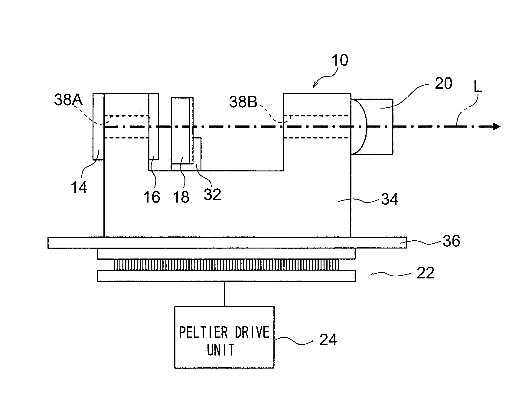
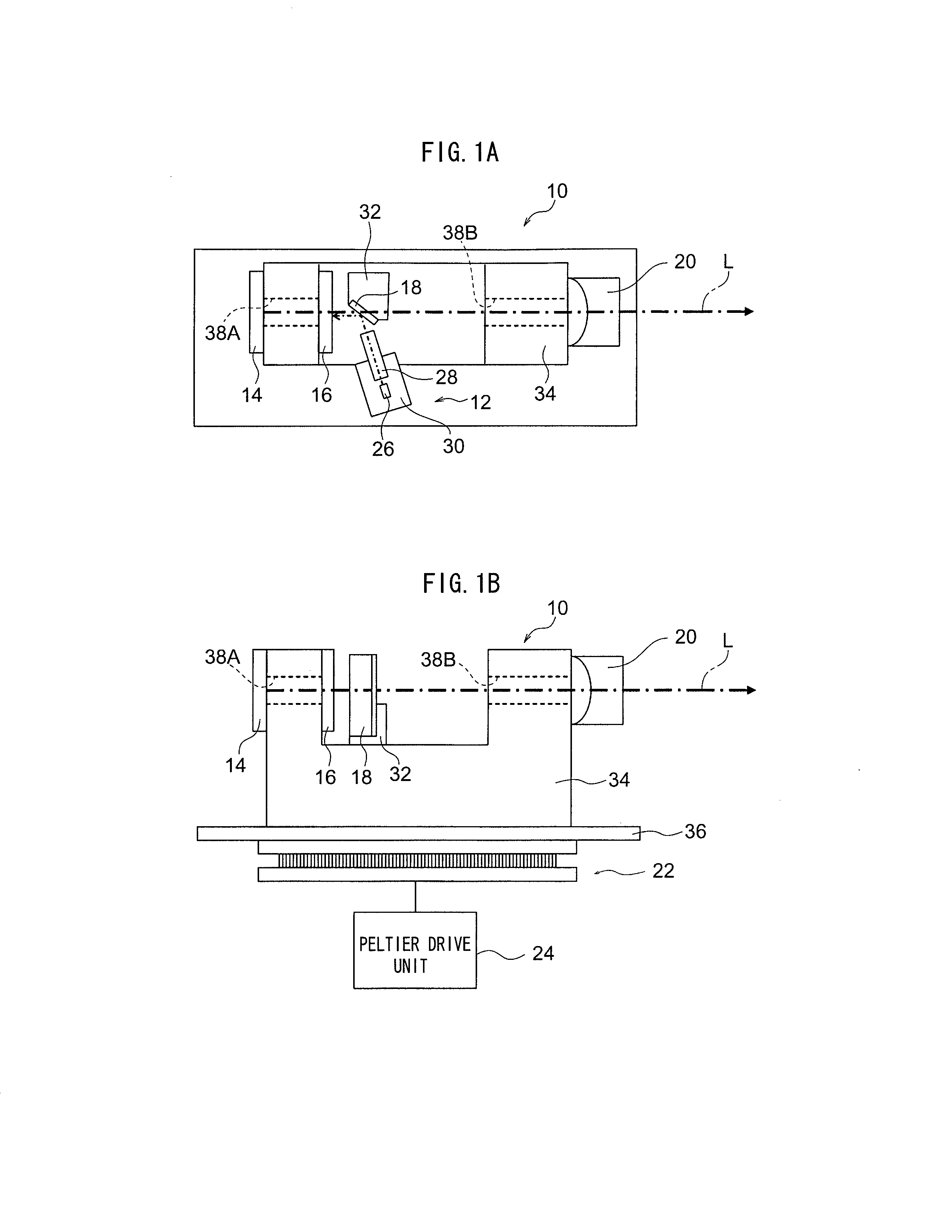
[0056]FIG. 1A is a schematic plan view of a mode-locked laser device 10, and FIG. 1B shows a schematic side view thereof. As shown in FIGS. 1A and 1B, the mode-locked laser device 10 is configured including: an excitation light optical system 12; a SESAM 14; a solid-state laser medium 16; a dichroic mirror 18; a resonance mirror 20; a Peltier device 22; and a Peltier drive unit 24.

[0057]As shown in FIG. 1A, the excitation light optical system 12 is configured including a semiconductor laser 26, serving as an excitation light source and a SELFOC lens 28, fixed, by for example adhesive, onto an excitation light optical system holder 30, configured by a component made from copper, for example.

[0058]A dichroic mirror holder 32, to which the SESAM 14, the solid-state laser medium 16, the resonance mirror 20, and the dichroic mirror 18 are attached, is fixed to a resonator holder 34, for example...

second exemplary embodiment

[0080]Explanation will now be given of the second exemplary embodiment of the present invention. Similar parts of the configuration to those of the first exemplary embodiment are allocated the same reference numerals and detailed explanation thereof is omitted.

[0081]FIGS. 4A and 4B show a schematic configuration of a mode-locked laser device 10A according to the second exemplary embodiment of the present invention. The mode-locked laser device 10A is of substantially the same configuration to that of the mode-locked laser device 10. Since only the characteristics of some of the optical elements differ the optical elements with different characteristics will be allocated a different reference number, and the other optical elements will be allocate the same reference numerals and explanation thereof omitted.

[0082]As the SESAM 14A, for example, one manufactured by BATOP GmbH, having a modulation depth (ΔR) of 0.5% to light of wavelength 1045 nm, a non-saturable loss (Rns) of 0.2%, and ...

third exemplary embodiment

[0092]Explanation will now be given regarding a third exemplary embodiment of the present invention. Similar parts of the configuration to those of the above exemplary embodiments are allocated the same reference numerals and detailed explanation thereof is omitted.

[0093]FIG. 6A is a schematic plan view of a mode-locked laser device 40 according to a third exemplary embodiment of the present invention, and FIG. 6B is a schematic side view thereof.

[0094]As shown in FIG. 6A, the mode-locked laser device 40 is configured including: a energizing light source 42; a λ / 2 plate 44; a mirror 46; a lens 48; a solid-state laser medium 50; a Littrow Prism 52; a Peltier device 22; and a Peltier drive unit 24.

[0095]A Nd:YVO4 laser (for example MILLENNIA IR, made by Spectra-Physics Co.) can, for example, be employed for the energizing light source 42.

[0096]The laser light output from the energizing light source 42 is polarized by the λ / 2 plate 44, and reflected by the mirror 46 in the direction to...


PUM


Abstract

There is provided a mode-locked laser including: a resonator having a pair of resonance mirrors; a solid-state laser medium, disposed in the resonator and outputting oscillating light due to excitation light being incident thereon; an excitation unit that causes the excitation light to be incident on the solid-state laser medium; a mode-locked element, disposed in the resonator for inducing mode locking; and a temperature adjusting unit that adjusts the temperature of the pair of resonance mirrors such that oscillating light of a specific frequency is output from the resonator.

Description

CROSS-REFERENCE TO RELATED APPLICATION[0001]This application is based on and claims priority under 35 USC 119 from Japanese Patent Application No. 2008-207582 filed on Aug. 12, 2008, the disclosure of which is incorporated by reference herein.BACKGROUND[0002]1. Technical Field[0003]The present invention relates to a mode-locked laser device, a pulsed laser light source device, and a microscope device. In particular the present invention relates to a resonator length adjustable mode-locked laser device, and a pulsed laser light source device and microscope device of the same.[0004]2. Related Art[0005]Recently, in many industries and academic disciplines, such as optical communication and optical data processing, applications of ultra high speed optical signals in picosecond and femtosecond ranges are rapidly expanding, and demand for devices that generate such ultra high speed optical signals has increased. The most basic form of such ultra high speed optical signals is a light pulse...

Claims


Application Information

Patent Timeline
IPC IPC(8): G01N21/64H01S3/098H01S3/04
CPCG01N21/6458G01N2021/653H01S3/025H01S3/0401H01S3/0405H01S3/1673H01S3/08004H01S3/09415H01S3/10046H01S3/1118H01S3/1611H01S3/042
Inventor YAMAZOE, SHOGO
Owner FUJIFILM CORP
Why Eureka
Try Eureka