Method of replacing an anterior cruciate ligament in the knee

a technology of anterior cruciate ligament and surgical procedure, which is applied in the direction of ligaments, prostheses, osteosynthesis devices, etc., can solve the problems of femoral and transverse tunnel interiors damage, grafts not being adequately secured, and the likelihood of a catastrophic failur

Active Publication Date: 2006-07-06
JOHNSON & JOHNSON INC (US)
View PDF38 Cites 239 Cited by
  • Summary
  • Abstract
  • Description
  • Claims
  • Application Information

AI Technical Summary

Benefits of technology

[0008] Therefore, a method for repairing a knee arthroscopically using an anterior cruciate ligament replacement graft is disclosed. The method consists of providing an anterior cruciate ligament replacement graft that is formed into a loop having a top and a bottom. The loop has an opening. A longitudinal tibial tunnel is drilled through a top of a tibia adjacent to the knee, the tibial tunnel has top and bottom openings. A longitudinal femoral tunnel is drilled through the bottom section of an adjacent femor such that the tibial tunnel and the femoral tunnel are substantially in alignment. The femoral tunnel has opposed top and bottom openings. A substantially transverse tunnel is drilled through the femoral tunnel such that the transverse tunnel intersects the femoral tunnel and is in communication therewith, the transverse tunnel has opposed first and second openings. A filamentary member is provided. The filamentary member is an endless loop. The filamentary member is threaded through knee such that a first end loop of the filamentary member extends out from a first side of the transverse tunnel, continues through the femoral and tibial tunnels, and a second end loop extends out through the bottom opening of the tibial tunnel. A surgical needle and suture are provided. The suture is mounted to the surgical needle such that a suture loop is formed. The graft is engaged with the suture loop such that the suture passes through the graft loop opening. And, the graft is also engaged with the second end loop of the filamentary member such that the filamentary member passes through the graft loop opening. The needle and suture are moved into the tibial tunnel and femoral tunnel. The graft loop is pulled into and partially out of the tibial tunnel by pulling on the needle and suture, such that the top of the graft loop is located outside of the top opening of the tibial tunnel and adjacent to the bottom opening of the femoral tunnel. The needle and suture move out through the top opening of the femoral tunnel. The filamentary member simultaneously moves with the graft as the suture is pulled. The second end loop of the filamentary member is also located outside of the top opening of the tibial tunnel adjacent to the bottom opening of the femoral tunnel. The first end loop of the filamentary member is then cut to form first and second ends. The first end of the filamentary member is maintained outside of the first opening of the tibial tunnel, and the filamentary member is manipulated to extend through the transverse tunnel with the second end of the filamentary member extending out through the second opening of the transverse tunnel. The suture is then tensioned to move the top of the graft loop and the second end loop of the filamentary member into to femoral tunnel such that the graft loop opening is in substantial alignment with the transverse tunnel. The filamentary member is tensioned to form a substantially straight configuration that is substantially in alignment with the transverse tunnel. A cannulated cross-pin is provided. The upper end of the graft loop is secured in the femoral tunnel by passing the cannulated bone pin over the filamentary member and mounting the bone pin in the transverse tunnel. The lower end of the graft loop may be secured in the tibial tunnel by inserting a securement member or device into the tibial tunnel, e.g. an interference screw, thereby completing the reconstruction.

Problems solved by technology

It can be appreciated by those skilled in this art that placement of the cross-pin above the top of the graft loop will result in the graft not being adequately secured in the femoral tunnel, with the likelihood of a catastrophic failure.
Although this method succeeds in emplacing a graft in the femoral tunnel and securing it with a cross-pin, there are disadvantages associated with its use.
This may result in damage to the bone surrounding the interiors of the femoral and transverse tunnels.
In addition, it can be a lengthy and time-consuming process since it is inefficient to move a graft longitudinally through a tunnel by pulling transversely on the flexible filamentary member.

Method used


Image

  • Method of replacing an anterior cruciate ligament in the knee
  • Method of replacing an anterior cruciate ligament in the knee
  • Method of replacing an anterior cruciate ligament in the knee

Examples


Embodiment Construction

[0025] The terms “anterior cruciate ligament” and the acronym “ACL” are used interchangeably herein.

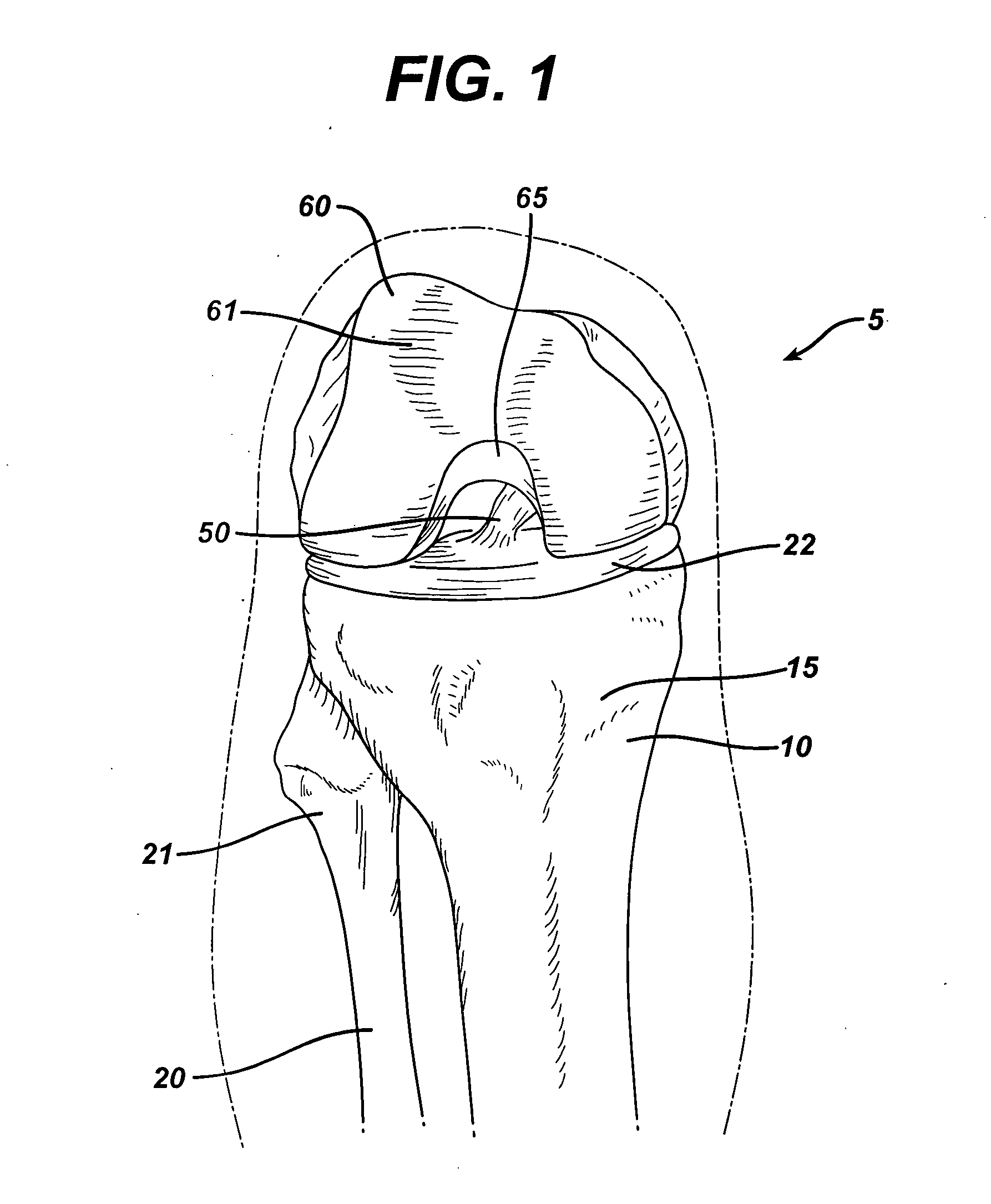
[0026] Referring now to FIGS. 1-15, the novel surgical method of the present invention of replacing a ruptured anterior cruciate ligament to reconstruct a knee is illustrated. FIG. 1 illustrates a typical patient's knee 5 prior to the onset of the surgical procedure. Illustrated is the top 15 of the tibia 10, the top 21 of the fibula 20, the bottom 61 of the femur 60, as well as the condylar notch 65. The posterior collateral ligament 50 is seen to be present in the knee 5. Also seen at the top 15 of the tibia 10 the meniscal cartilage 22.

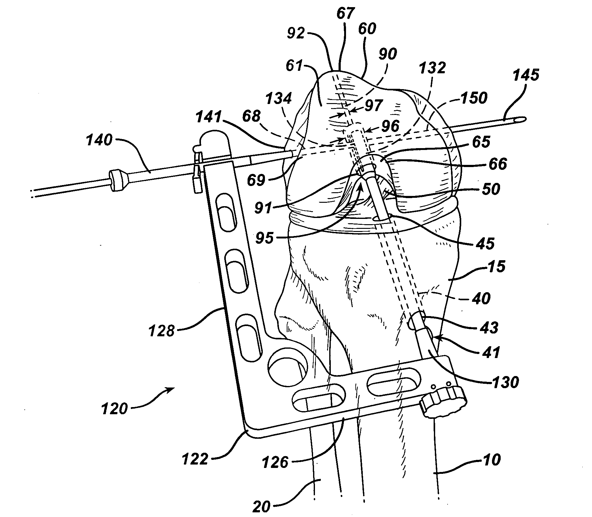
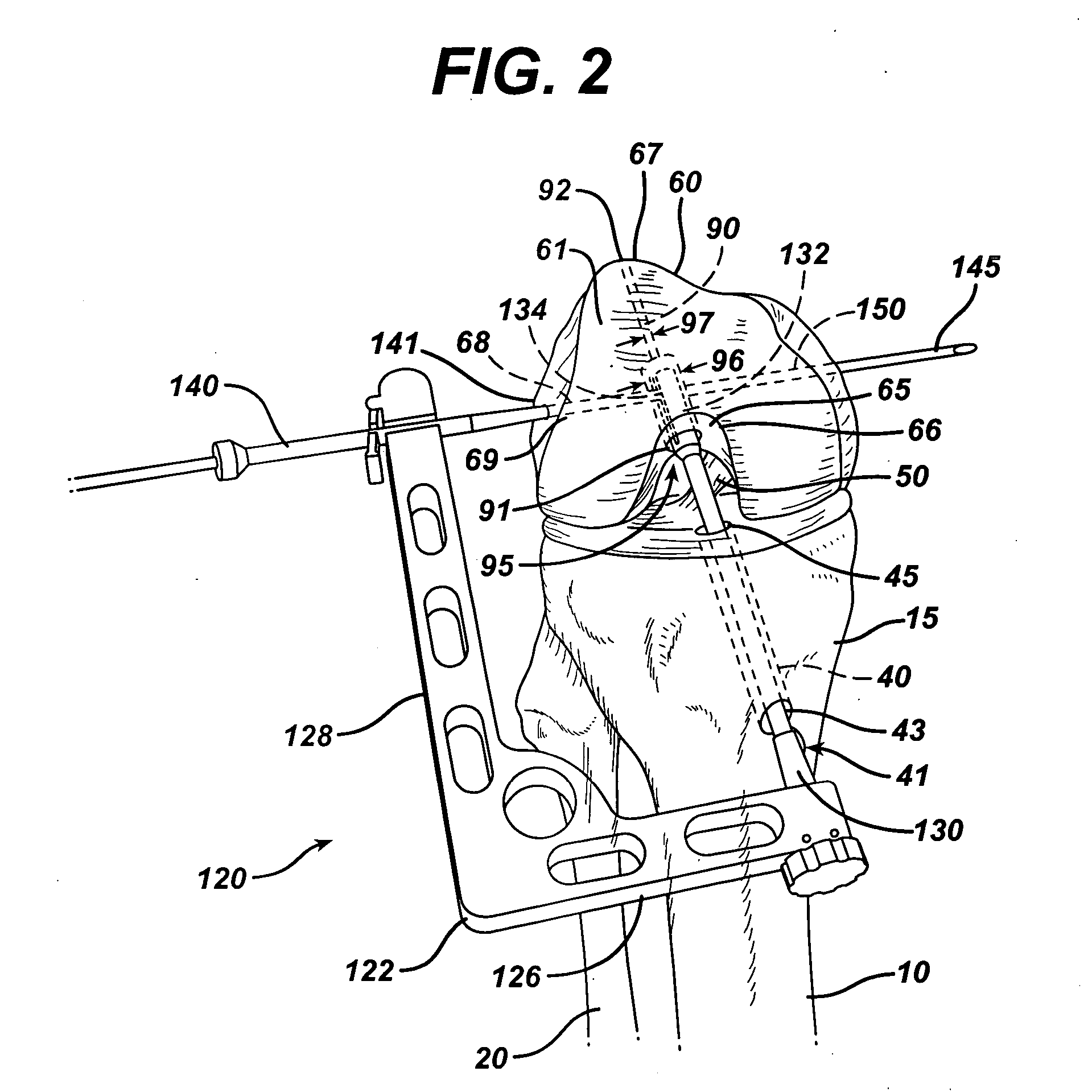
[0027] As seen in FIG. 2, after preparing the patient's knee 5 using conventional arthroscopic surgical procedures, a tibial tunnel 40 is drilled in a conventional manner through the top 15 of the tibia 10 to create tibial tunnel 40. Tibial tunnel 40 has passage 41 having lower opening 43 and upper opening 45. The tibial tunnel 40 is drilled using ...


PUM


Abstract

A method of reconstructing a ruptured anterior cruciate ligament in a human knee. Femoral and tibial tunnels are drilled into the femur and tibia. A transverse tunnel is drilled into the femur to intersect the femoral tunnel. A filamentary loop is threaded through the femoral tunnel and tibial tunnel and partially through the transverse tunnel. A replacement graft is formed into a loop and moved into the tibial tunnels using a surgical needle and suture. A flexible filamentary member is simultaneously moved along with the loop into the femoral and transverse tunnels. The filamentary member is used as a guide wire in the transverse tunnel to insert a cannulated cross-pin to secure a top of the looped graft in the femoral tunnel.

Description

TECHNICAL FIELD [0001] The field of art to which this invention relates is arthroscopic surgical procedures, in particular, arthroscopic surgical procedures for replacing an anterior cruciate ligament in the knee. BACKGROUND OF THE INVENTION [0002] Arthroscopic surgical repairs of a ruptured anterior cruciate ligament in the knee are known in this art. A rupture of the anterior cruciate ligament (“ACL”) is often seen in sports related injuries. In a typical arthroscopic procedure, the surgeon prepares the patient for surgery by insufflating the patient's knee with sterile saline solution. Several cannulas are inserted into the knee and used as entry portals into the interior of the knee. A conventional arthroscope is inserted through one of the cannulas so that the knee may be remotely viewed by the surgeon. The surgeon then drills a tibial tunnel and a femoral tunnel in accordance with conventional surgical techniques using conventional surgical drills and drill guides. A replaceme...

Claims


Application Information

Patent Timeline
Patent Type & Authority Applications(United States)
IPC IPC(8): A61B17/60
CPCA61B17/1714A61B17/1764Y10S623/911Y10S623/908
Inventor MAY, THOMAS C.WHITTAKER, GREGORY
Owner JOHNSON & JOHNSON INC (US)
Why Eureka
Try Eureka