
Vehicle for running on rail

a technology for running vehicles and rails, applied in the direction of elevated railways, transportation and packaging, locomotives, etc., can solve the problems of reduced gripping force, easy slippage on rails, and easy slippage, so as to improve the effect of elastic deformation, efficient and smooth running of the vehicle, and moderate gripping for

Inactive Publication Date: 2006-07-13
SENYO KIKO
View PDF5 Cites 1 Cited by
  • Summary
  • Abstract
  • Description
  • Claims
  • Application Information

AI Technical Summary

Benefits of technology

[0008] In view of the above problems, a primary concern of the present invention is to provide a vehicle for running on a rail having the capability of moderately generating a grip force of a wheel (drive wheel) on the rail according to a total weight of the vehicle (including loads), and realizing efficient and smooth running, despite its relatively simple structure.
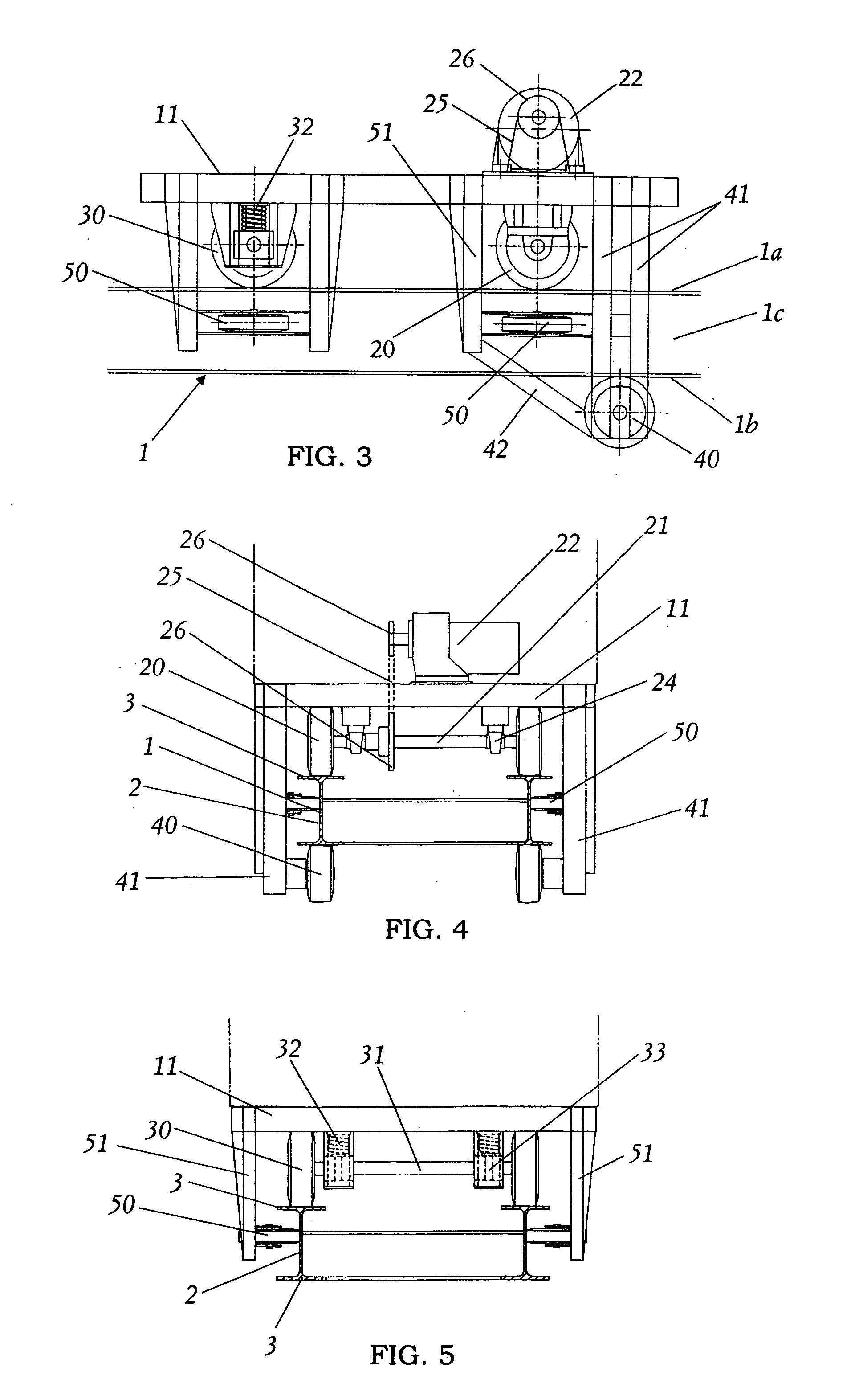
[0010] According to the present invention, when the cushioning member such as a coil spring is elastically deformed downward by receiving a weight of the vehicle and loads carried on the vehicle, the vehicle takes an inclined posture such that the second wheel side having the cushioning member of the base comes close to the rail. At this time, the third wheel positioned at a side opposed to the second wheel through the first wheel is pressed against the lower surface of the rail according to the principle of leverage with a fulcrum that is the contact point between the first wheel and the rail. Thereby a force for holding the rail between the first wheel and the third wheel, i.e., the gripping force is obtained. In addition, since an amount of the elastic deformation of the cushioning member, i.e., an inclination degree of the vehicle changes according to the weight of received from the vehicle, the rail gripping mechanism of the present invention can provide a moderate gripping force according to the vehicle's weight. Therefore, when the elastic deformation capability of the cushioning member and the position of the third wheel are appropriately determined, it is possible to provide the moderate gripping force between the wheel and the rail according to the weight of the vehicle (including the loads) without using a special device for monitoring the vehicle's weight and controlling the spring constant of the spring member for pressing the wheel against the rail according to the monitored weight. As a result, it is possible to provide efficient and smooth running of the vehicle.
[0011] In a preferred embodiment of the present invention, a distance between the first wheel and a center of gravity of the vehicle in a running state is greater than the distance between the second wheel and the center of gravity, and shorter than the distance between the third wheel and the center of gravity. In this case, since the second wheel is disposed in the vicinity of the center of gravity of the vehicle, the cushioning member can be elastically deformed more effectively at a slope region of the rail to obtain the gripping force.
[0012] In addition, it is preferred that the third wheel is comprised of at least two wheels spaced from each other in the extending direction of the rail. In this case, since the plural third wheels contact the lower surface of the rail, it is possible to increase the friction resistance, and further improve the gripping performance on the rail.
[0013] Moreover, it is preferred that the vehicle has an auxiliary wheel held by the base to be rotatable on a side surface of the rail under at least one of the first and second wheels. In this case, since the first and second wheels are guided to prevent derailment, the running safety of the vehicle can be further improved.

Problems solved by technology

In a vehicle for running on rail, there is a case that a reduction in grip force that is friction resistance between a drive wheel and the rail poses a problem for the vehicle's running.
For example, slippage easily occurs on the rail in the rain.
In particular, when the vehicle runs on an inclined rail in the rain, it becomes a serious problem.
However, an excessive increase in the grip force leads to an increase in energy needed for the vehicle's running.
As a result, it becomes difficult to provide efficient running of the vehicle on the rail.
However, there are problems that the control becomes complex, and a total cost of the vehicle track system increases.
However, in such a track device, it is needed to manufacture the rails having different widths every curve region.
Therefore, when a total length of the rail is long, or many curve regions are designed in the track device, an increase in cost of the track device is unavoidable.
Thus, from the viewpoints of considering the cost performance of the entire track device, and providing smooth running of the vehicle, while moderately maintaining the grip forces of the wheels on the rail, there is still plenty of room for improvement in the conventional vehicle for running on rail and the system using an expensive control unit or the design change of the rails.

Method used


Image

  • Vehicle for running on rail
  • Vehicle for running on rail
  • Vehicle for running on rail

Examples


Embodiment Construction

[0024] A vehicle for running on rails of the present invention is explained in detail according to preferred embodiments, referring to the attached drawings.

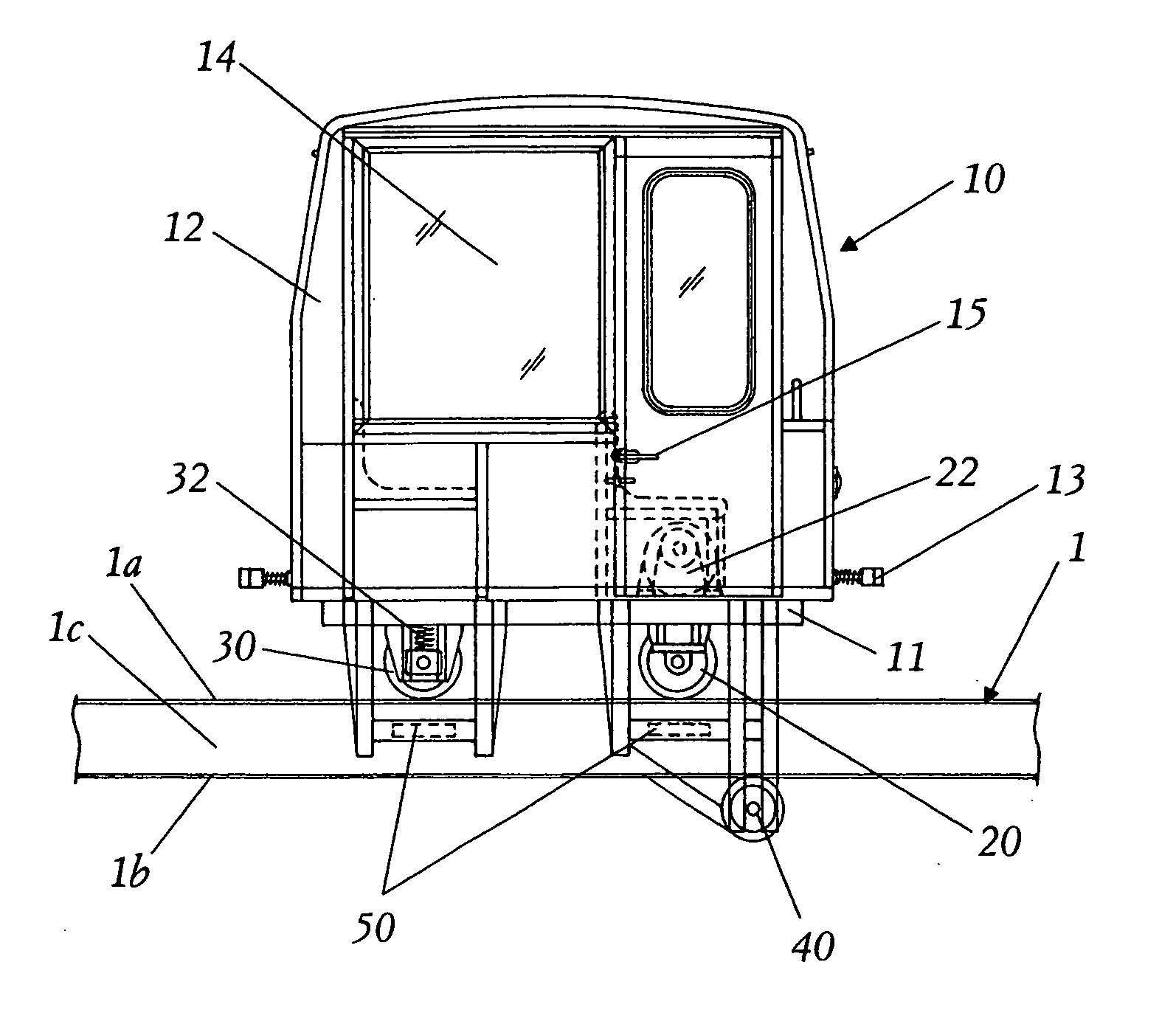
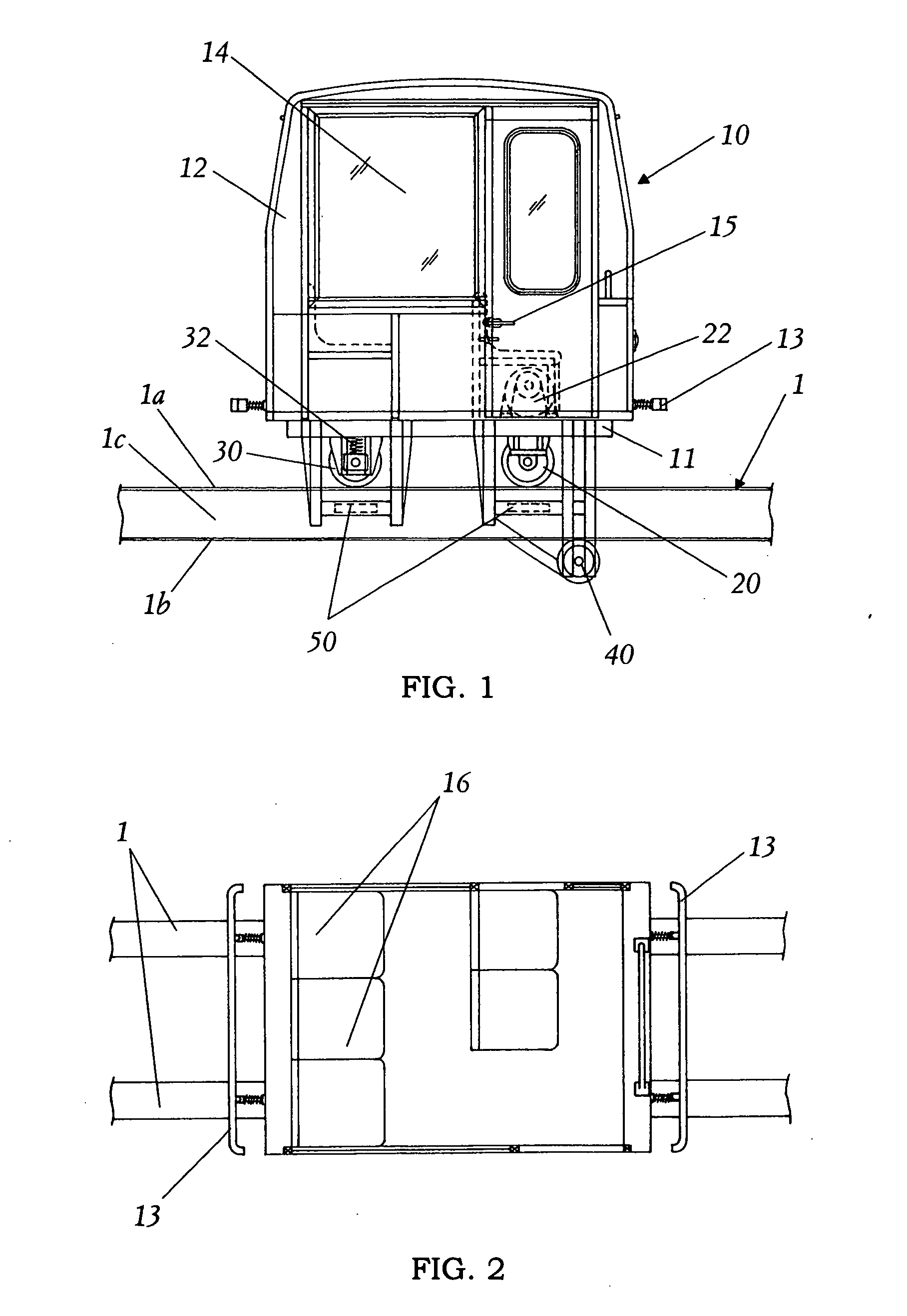
[0025] As shown in FIGS. 1 and 2, the vehicle 10 for running on rails of this embodiment has the capability of running on a pair of rails 1 extending in parallel to each other in the forward and backward directions. The vehicle is formed with a base 11, a body 12 disposed on the base to provide a passenger cabin, a pair of first wheels 20 held by the base to run on upper surfaces 1a of the rails 1, a pair of second wheels 30 held by the base to run on the upper surfaces 1a of the rails 1 and spaced from the first wheels in the extending direction of the rails, a pair of thirds wheels 40 held by the base to run on lower surfaces 1b of the rails 1, four auxiliary wheels 50 held by the base to run on side surfaces 1c of the rails 1 under each of the first and second wheels, and a motor 2 for driving the first wheels 20. As shown i...


PUM


Abstract

A vehicle for running on rail is provided, which has the capability of achieving smooth running, while moderately gripping the rail. This vehicle has a base, a pair of first and second wheels held by the base to be rotatable on an upper surface of the rail and spaced from each other in an extending direction of the rail, a third wheel held by the base to be rotatable on a lower surface of the rail, and a motor for rotating the first wheel. The first wheel is positioned between the second and third wheels in the extending direction of the rail, and the second wheel is held by the base through a cushioning member. When the vehicle is tilted due to an elastic deformation of the cushioning member for the second wheel, gripping forces of the first and third wheels on the rail increase.

Description

TECHNICAL FIELD [0001] The present invention relates to a vehicle for running on rail (tracked vehicle), and particularly the vehicle having the capability of providing smooth running, while moderately maintaining a grip force on the rail. BACKGROUND ART [0002] In a vehicle for running on rail, there is a case that a reduction in grip force that is friction resistance between a drive wheel and the rail poses a problem for the vehicle's running. For example, slippage easily occurs on the rail in the rain. In particular, when the vehicle runs on an inclined rail in the rain, it becomes a serious problem. [0003] To solve this problem, it is needed to increase the grip force by pressing the drive wheel against the rail. However, an excessive increase in the grip force leads to an increase in energy needed for the vehicle's running. As a result, it becomes difficult to provide efficient running of the vehicle on the rail. [0004] In addition, to obtain a moderate grip force, it has been p...

Claims


Application Information

Patent Timeline
IPC IPC(8): B61C13/00B61B13/00B61B13/06B61C13/04
CPCB61C13/04B61B5/00B61B13/04B61J1/12
Inventor YAMADA, SABURO
Owner SENYO KIKO
Learn More