Diagnostic system for detecting rupture or thinning of diaphragms

a technology of diaphragm and diagnostic system, which is applied in the direction of resistance/reactance/impedence, instruments, fluid pressure measurement, etc., can solve the problems of fill fluid leakage and contamination of the process

Active Publication Date: 2006-07-13
ROSEMOUNT INC
View PDF30 Cites 20 Cited by
  • Summary
  • Abstract
  • Description
  • Claims
  • Application Information

AI Technical Summary

Problems solved by technology

Additionally, fill fluid from the fluid filled capillary may escape through a rupture in the isolating diaphragm to contaminate the process.
Howeve...

Method used


Image

  • Diagnostic system for detecting rupture or thinning of diaphragms
  • Diagnostic system for detecting rupture or thinning of diaphragms
  • Diagnostic system for detecting rupture or thinning of diaphragms

Examples


Embodiment Construction

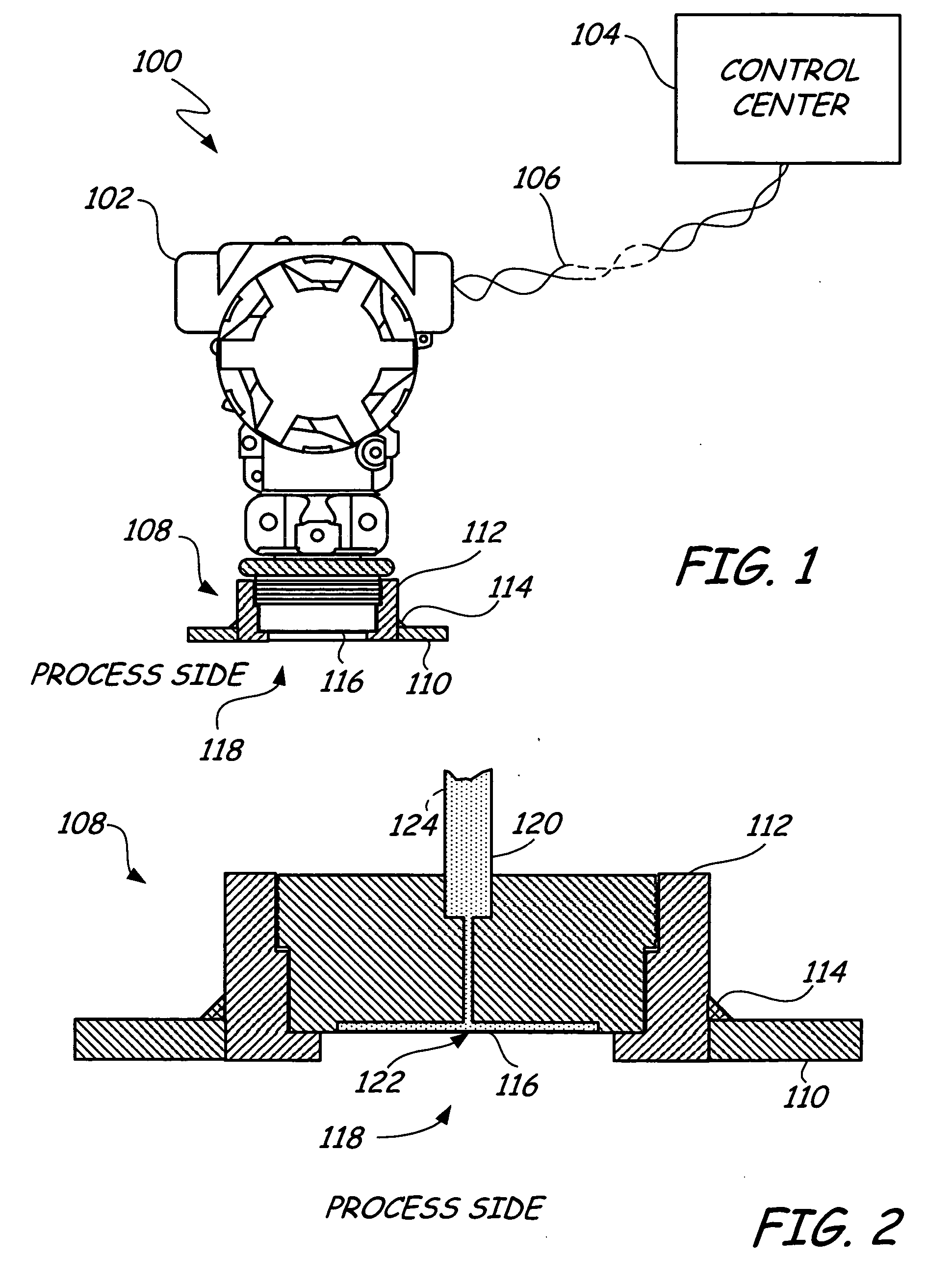
[0016]FIG. 1 is a simplified diagram of an industrial process transmitter with a rupture detection feature according to an embodiment of the present invention. The system 100 includes a transmitter 102 communicatively coupled to a control center 104 by a communications link 106, which may be wired or wireless. The communications link 106 couples electronics disposed within the housing of the transmitter 102 to monitoring and control systems in the control center 104.

[0017] Additionally, a base portion 108 of the transmitter 102 is coupled to a wall 110 of an industrial process vessel by a weld spud 112, which is welded to the vessel wall 110 at a weld joint 114. The transmitter 102 is threadably coupled to the weld spud 112 such that the isolating diaphragm 116 is directly exposed to process fluid within the vessel via an opening 118 in the vessel wall 110.

[0018]FIG. 2 is an expanded cross sectional view of the base portion 108 of the transmitter 102 of FIG. 1. The base portion 10...


PUM


Abstract

A diaphragm diagnostic system for use in an industrial field device has a diaphragm and a diagnostic feature. The diaphragm is configured to couple the field device to a process fluid and has a plurality of layers. A first layer of the plurality of layers is exposed to process fluid of an industrial process. A diagnostic feature is coupled to the diaphragm to monitor an electrical parameter of the diaphragm and responsively infer an operative state of the diaphragm based on a change in the monitored electrical parameter.

Description

BACKGROUND OF THE INVENTION [0001] The present invention relates to diaphragms for use in industrial process instrumentation, and more particularly, to a diagnostic system for detecting rupture or thinning of diaphragms. [0002] Many industrial instruments include a diaphragm element coupled to an industrial process for measuring a parameter of the process. For example, some pressure transmitters include an isolating diaphragm that is coupled to an industrial process. Pressure measurements may be taken directly from the diaphragm based on the diaphragms deflection in response to pressure or may be taken indirectly by a remote pressure sensor that is coupled to the isolating diaphragm by a fluid filled capillary. Rupture or thinning of the diaphragm can alter measurement readings, and / or permit process fluid to escape from the industrial process. Additionally, fill fluid from the fluid filled capillary may escape through a rupture in the isolating diaphragm to contaminate the process....

Claims


Application Information

Patent Timeline
IPC IPC(8): G08B21/00G01R27/26
CPCG01N27/24G01L27/007H05K7/1462
Inventor ANDERSON, WILLIAM THOMASWELLS, CHRISTOPHER ASHLEY
Owner ROSEMOUNT INC
Why Eureka
Try Eureka