

Antenna and electronic equipment
a technology of electronic equipment and antennas, applied in the field of antennas, can solve the problems of difficult to broaden the bandwidth and inability to secure the distance, and achieve the effect of multiple resonances
- Summary
- Abstract
- Description
- Claims
- Application Information
AI Technical Summary
Benefits of technology
Problems solved by technology
Method used
Image

Examples
first exemplary embodiment
[0016]
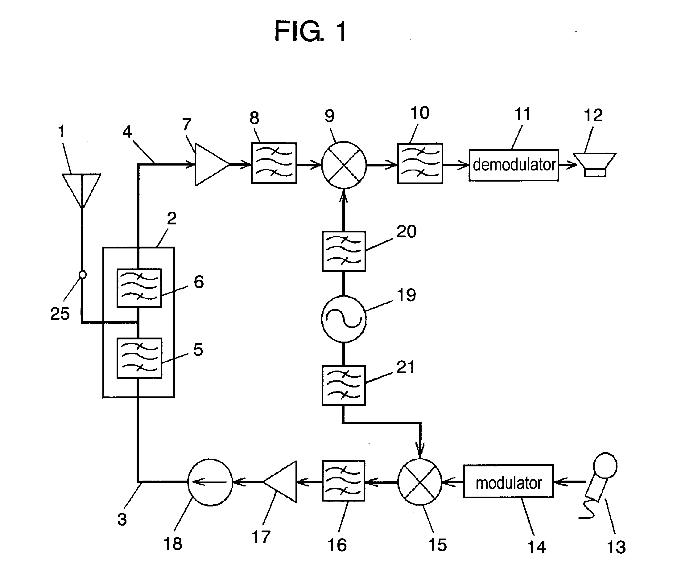
[0017]FIG. 1 shows an electric circuit of a portable phone. As shown in FIG. 1, antenna 1 is connected to transmission line 3 and reception line 4 via antenna duplexer 2. Antenna duplexer 2 includes transmission filer 5 and reception filter 6. Electric wave received by antenna 1 is transmitted to reception line 4 via antenna duplexer 2, whereas transmission signals such as voice are transmitted from antenna 1 via transmission line 3 and antenna duplexer 2. The electric circuit of the portable phone shown in FIG. 1 is a general example, so it will be described only briefly. Reception line 4 is connected with speaker 12 via amplifier 7, interstage filter 8, mixer 9, IF filter 10 and demodulator 11. On the other hand, transmission line 3 has modulator 14, mixer 15, interstage filter 16, amplifier 17 and isolator 18 provided thereon in that order from microphone 13, and is connected to antenna duplexer 2. Mixers 9 and 15 are connected to voltage control oscillator (VCO) 19 via fil...
second exemplary embodiment
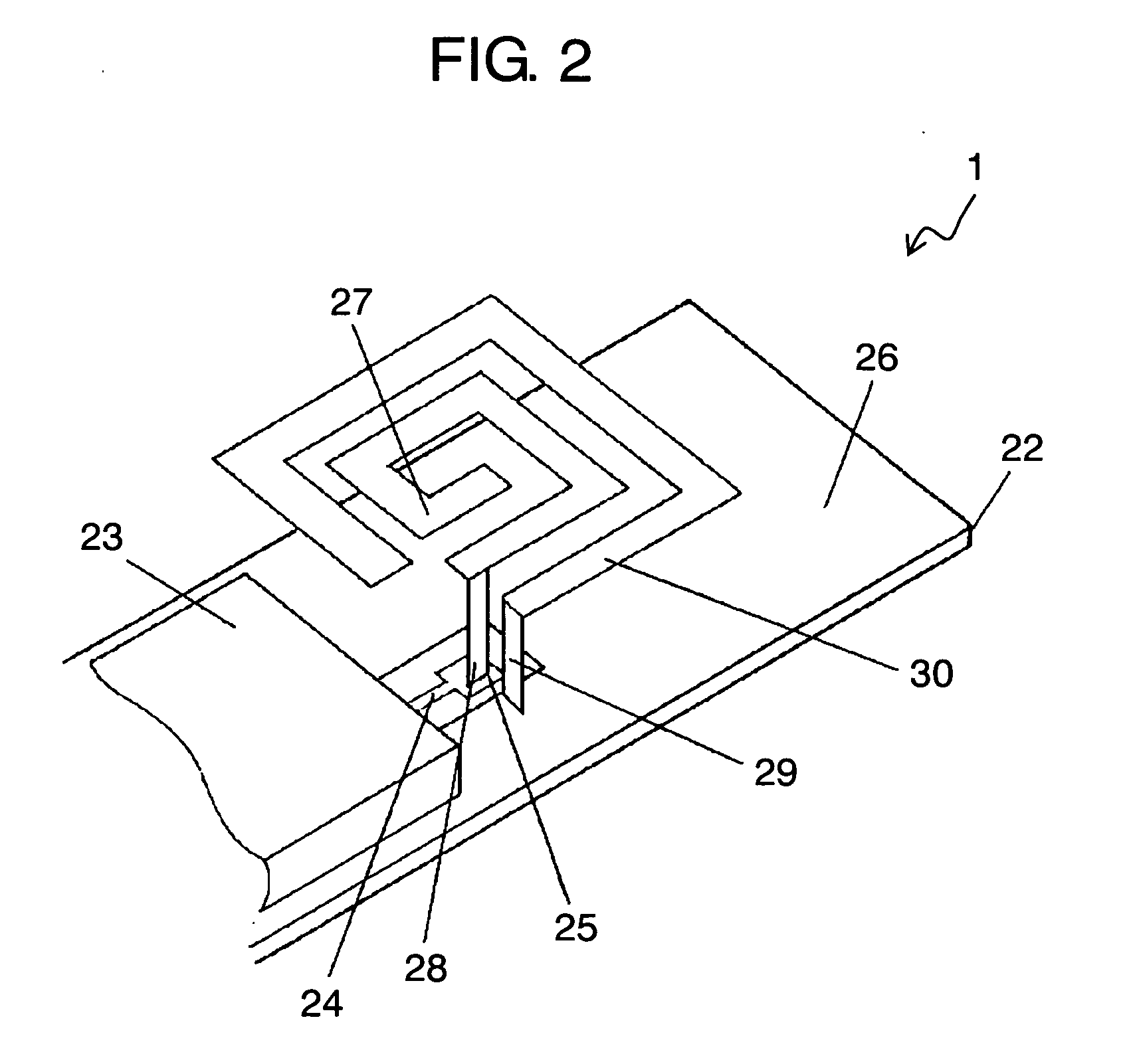
[0024]FIG. 5 shows antenna 51 of a second embodiment of the present invention.
[0025] Antenna 51 includes ground plate 26; first power feed element 27 which is projected from an end of ground plate 26 within the same plane as ground plate 26 and which is formed in a meander shape; and power feed part 28 which electrically connects ground plate 26 and first power feed element 27. Antenna 51 further includes first parasitic element 30 which faces first power feed element 27 with a predetermined distance therebetween. The first parasitic element is projected in the same direction as first power feed element 27, and is electrically connected with ground plate 26 via first shortcircuit part 29 provided at an end of the first parasitic element 30. In the secondt embodiment, the distance between first power feed element 27 and the first parasitic element 30 can be secured by disposing first parasitic element 30 lower than ground plate 26. Besides this solution, the in-between distance can ...
third exemplary embodiment
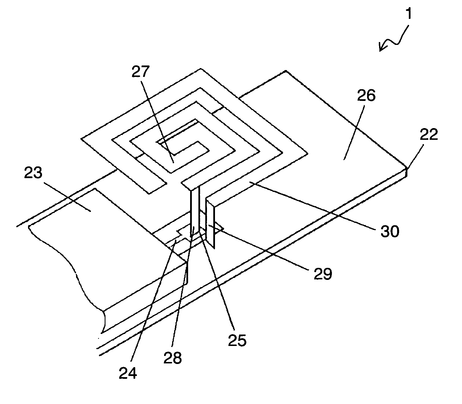
[0028]FIG. 6 shows antenna 61 of a third embodiment of the present invention.
[0029] Antenna 61 includes ground plate 26; first power feed element 27 which is disposed to face ground plate 26 and which is formed in a spiral shape; second power feed element 31 branched from first power feed element 27; power feed part 28 which feeds high frequency signals into first power feed element 27 and second power feed element 31; first parasitic element 30 which is disposed to surround first power feed element 27 with a desired distance therebetween; second parasitic element 32 which is branched from first parasitic element 30 and which is disposed separately from second power feed element 31 by a desired distance; and first shortcircuit part 29 which electrically connects first and second parasitic elements 30, 32 and ground plate 26.
[0030] Such use of first and second power feed elements 27, 31 and first and second parasitic elements 30, 32 makes it possible to broaden bandwidths in the fr...
PUM
 Abstract
Description
Claims
Application Information